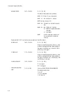
Command Codes (AVM-510A)
E-7
H8
m bit0 color frame display on
m bit1 VITC time code on
m bit2 graticule off
m bit3 PAL graticule in percent
H9
m bit0 LED reduced size WFM
m bit1 LED reduced size VEC
m bit2 system in 625 line mode
m bit3 measurement set 2 active
H POS NOTIFY
‘H’N . .N<CR>
N. .N = [0. .999]
Response to H POS REQUEST. This is a
normalized position, that is, a value of 500
would put the slider in the middle of the
range. 0 is all the way to the left; 999 is all
the way to the right.
V POS NOTIFY
‘V’N . .N<CR>
N. .N = [0. .999]
Response to V POS REQUEST. This is a
normalized position, that is, a value of 500
would put the slider in the middle of the
range. 0 is all the way to the bottom; 999 is
all the way to the top.
VECTOR PHASE
NOTIFY
‘P’N . .N<CR>
N. .N = [0. .999]
This is a normalized position, that is, a value
of 500 would put the slider in the middle of
the range.
VAR GAIN NOTIFY
‘G’N. .N<CR>
N. .N = [0. .255]
Response to VAR GAIN REQUEST.
0 = least gain
255 = most gain
SELECTED LINE
NOTIFY
‘L’S. .S<CR>
Response to SELECTED LINE REQUEST.
MEASURE LINE
NOTIFY
‘N’S. .S<CR>
Response to MEASURE LINE REQUEST.
Summary of Contents for MM-410
Page 16: ...About This Manual 1 4 Notes...
Page 34: ...Installation 4 6 Notes...
Page 48: ...Front Panel Operation 5 14 Notes...
Page 102: ...Viewing Waveforms Vectors and Pictures 7 30 Notes...
Page 126: ...Automatic Measurement AVM 510A 9 20 Notes...
Page 148: ...AVM 510A C For Component Measurements 12 4 Notes...
Page 158: ...Connector Pinouts B 4 Notes...
Page 162: ...Calibration D 2 Notes...

