Product Overview (MM-410)
2-6
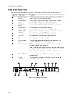
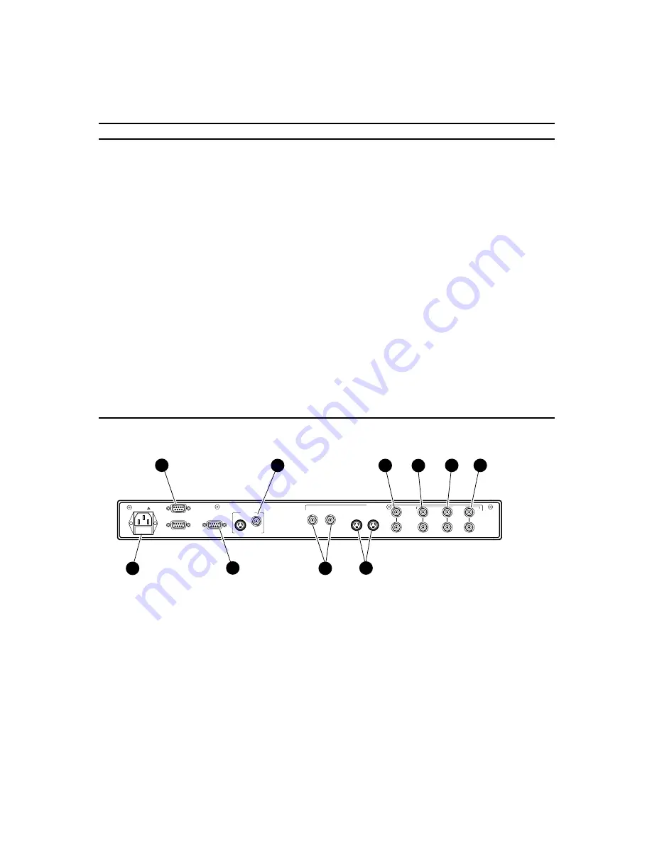
MM-410 Rear View
The following cable connectors can be viewed from the rear of the MM-410 (see Figure 2-2).
Legend
Connector
Function
1
RS-232
Lets you connect to a PC for system updates.
2
Picture monitor
outputs
These outputs (S-video and composite) are available for a picture
monitor display of a picture, waveforms, or signal status.
3
Composite (A)
One switchable loop-through composite input.
4
Composite (B),
CPST or G/Y
One switchable loop-through composite, CPST, or G/Y component
input.
5
CNPT (B)
One switchable loop-through B/B-Y component input.
6
CNPT (B)
One switchable loop-through R/R-Y component input.
7
Power
Line voltage power connector (ac input).
8
DC control
Lets you select any of the first four memories by grounding (earthing)
pins 1 through 4.
Refer to Chapter 4, “Installation,” for additional information on this
connector.
9
External reference
A composite analog external reference signal representing studio
reference timing.
:
S-video
(A or B)
One switchable loop-through S-video input. Can only be selected
using the Input menu options.
ALARM
RS232
COMPUTER
OUTPUTS
EXT REF
S-VIDEO (A or B)
COMPOSITE (A)
VIDEO INPUTS
MAGNI SYSTEMS INC., USA
MM-002
9
10
POWER
DC CONTROL
S-VIDEO
CPST
PICTURE MONITOR
COMPOSITE (B)
CPNT (B)
CPST
or G/Y
B/B-Y
R/R-Y
3
4
5
6
2
1
7
8
Figure 2-2. MM-410 Rear View
Summary of Contents for MM-410
Page 16: ...About This Manual 1 4 Notes...
Page 34: ...Installation 4 6 Notes...
Page 48: ...Front Panel Operation 5 14 Notes...
Page 102: ...Viewing Waveforms Vectors and Pictures 7 30 Notes...
Page 126: ...Automatic Measurement AVM 510A 9 20 Notes...
Page 148: ...AVM 510A C For Component Measurements 12 4 Notes...
Page 158: ...Connector Pinouts B 4 Notes...
Page 162: ...Calibration D 2 Notes...

