Viewing Waveforms, Vectors, and Pictures
7-5
Setting Waveform Limit Lines
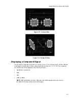
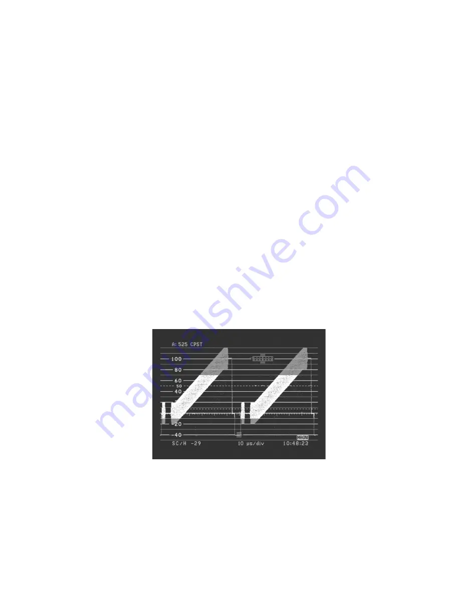
Waveform limit lines show any part of the input signal that goes above or below a pre-determined set
of limits. Note that these limits are shown relative to the signal blanking level, not the graticule, so
moving the waveform up or down does not move the beginning of the red area (see Figure 7-4).
To set waveform limit line values or to toggle this feature on and off:
1.
Press the
Config
button to access the Configure menu.
2.
Select DISPLAY and then press the
Enter
button.
3.
Select WFM LIMIT LINE and then press the
Enter
button.
4.
To turn WFM LIMIT LINE ON or OFF, select OUT OF LIMIT LINE and then press the
Enter
button or turn the knob.
5.
To set an upper or lower limit line, select either UPPER LIMIT LINE or LOWER LIMIT LINE and
then press the
Enter
button or turn the knob.
The red limit portion of the display is not affected by the vertical postion of the waveform. However,
the limit line border is affected by variable gain. Increasing the variable gain causes either end of the
waveform to turn red.
If the limit line feature is on when you switch to vertical magnification, the limit line feature turns off.
When you turn off vertical magnification, the limit line comes back on.
Limit lines also work with Luma and Parade filters, but not with the Chroma filter alone. Use caution
when working with a Parade filter. In this case, the limit line border is attached to the unfiltered
waveform on the left of the display. Moving it separately up and down moves the red border of all
three waveforms. In addition, moving the two filtered waveforms separately can move them in or out
of the red area.
Figure 7-4. Waveform Limit Lines at 70 and –10 IRE
Summary of Contents for MM-410
Page 16: ...About This Manual 1 4 Notes...
Page 34: ...Installation 4 6 Notes...
Page 48: ...Front Panel Operation 5 14 Notes...
Page 102: ...Viewing Waveforms Vectors and Pictures 7 30 Notes...
Page 126: ...Automatic Measurement AVM 510A 9 20 Notes...
Page 148: ...AVM 510A C For Component Measurements 12 4 Notes...
Page 158: ...Connector Pinouts B 4 Notes...
Page 162: ...Calibration D 2 Notes...


