OPERATION
67
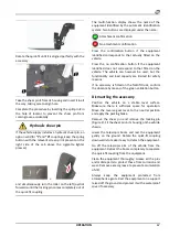
Rotate the quick-fit until it is aligned perfectly with the
accessory.
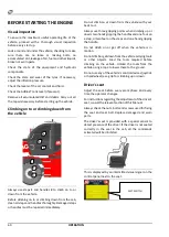
Take the shear pin
1
from its housing and insert it in all
the way, taking care to align hole.
Complete the procedure by inserting the split pin
2
in
the hole of locator to prevent the shear pin from
coming loose accidentally.
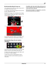
Hydraulic shear pin
If the vehicle supply includes a hydraulic shear pin, an
option valid for
“I”
and
“U”
couplings, keep the spring
button with the relevant screen print present on the
right side of the cab above the cigarette lighter
pressed,
+
and simultaneously turn the roller on the left joystick
forwards until the locking pin comes completely out of
the quick-fit coupling.
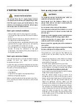
The multi-function display shows the name of the
equipment identified by the automatic identification
system. Two buttons are displayed under the name:
Attachment confirmation
No attachment confirmation
Press the confirmation button if the equipment
identified corresponds to that actually fitted on the
vehicle.
Press the no confirmation button if the equipment
identified does not correspond to that fitted on the
vehicle. The vehicle can however be used, but the
functionality and load capacity are limited for safety
reasons.
If no accessory is fitted on the forklift truck, confirm
the absence by means of the green validation button.
Dismantling the accessory
Position the vehicle on a stable level surface.
Make sure there is sufficient space for operation.
Move the reverse gear lever to the neutral position
and apply the parking brake.
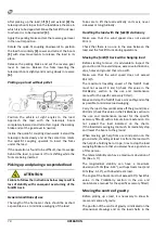
Remove the shear pin and remove the locking pin
(Figure 2). Fit the shear pin in its housing on the vehicle
chassis.
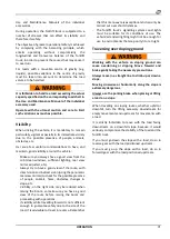
Lower the telescopic boom and rest the equipment
gently on the ground. Rotate the quick-fit coupling
downwards to make it easy to detach the equipment.
Go off the telescopic arm of the vehicle from the
equipment. Retract the boom completely to separate
the quick-fit coupling from the equipment.
Clean the equipment thoroughly. Grease all the pins
and mobile parts to protect these from corrosion and
wear. Remove excess grease to prevent accumulation
of dirt.
Always keep the equipment protected from
atmospheric agents. Rest the equipment on a support
raised off the ground and protect it with a waterproof
cover if necessary.
Summary of Contents for RTH 4.18
Page 6: ......
Page 27: ...SECTION ON PRODUCT INFORMATION 27 DIMENSIONS RTH 4 18 RTH 5 18 ...
Page 28: ...28 SECTION ON PRODUCT INFORMATION RTH 5 21 RTH 5 23 ...
Page 29: ...SECTION ON PRODUCT INFORMATION 29 RTH 5 25 RTH 6 21 ...
Page 30: ...30 SECTION ON PRODUCT INFORMATION RTH 6 23 RTH 6 25 ...
Page 78: ......


