background image

INSTRUCTIONS FOR USE AND WARNINGS 


11

Only transport loads that are properly balanced;
The  equipment  must  be  lowered  to  the  ground  in 


a hazard-free area devoid of obstacles;
The empty hook must be lowered gently, to prevent 

abnormal stresses on the rope which can damage the 

rope itself or the equipment structure;
Never  leave  the  forklift  truck  parked  with  a  raised 

load;
The operator must stop using the vehicle if visibility 

and lighting conditions are poor;
While working at heights, check constantly to make 

sure the wind speed never exceeds 45 km/h (28 mph).
In  case  of  strong  wind,  retract  the  equipment 

immediately, as the specific wind pressure on hanging 

loads  can  overload  the  forklift  truck  and  affect  its 

stability;
Avoid  using  the  equipment  in  especially  adverse 

weather  conditions  (rain  storms  in  the  presence  of 

lightning);
The  forklift  truck,  carrying  equipment  fitted  with 

ropes,  must  be  inspected  periodically  as  envisaged 

for lifting equipment, in compliance with legislation, 

provisions and regulations applicable in the country 

of  use.  The  user  alone  is  responsible  for  ensuring 

compliance with the legislation in force;
Before  starting  work  with  the  equipment  or  other 

lifting  equipment  with  hook,  inform  the  authorities 

responsible for inspections in your area;
Request  the  body  responsible  in  the  country  of 

operation for yearly inspections.

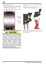
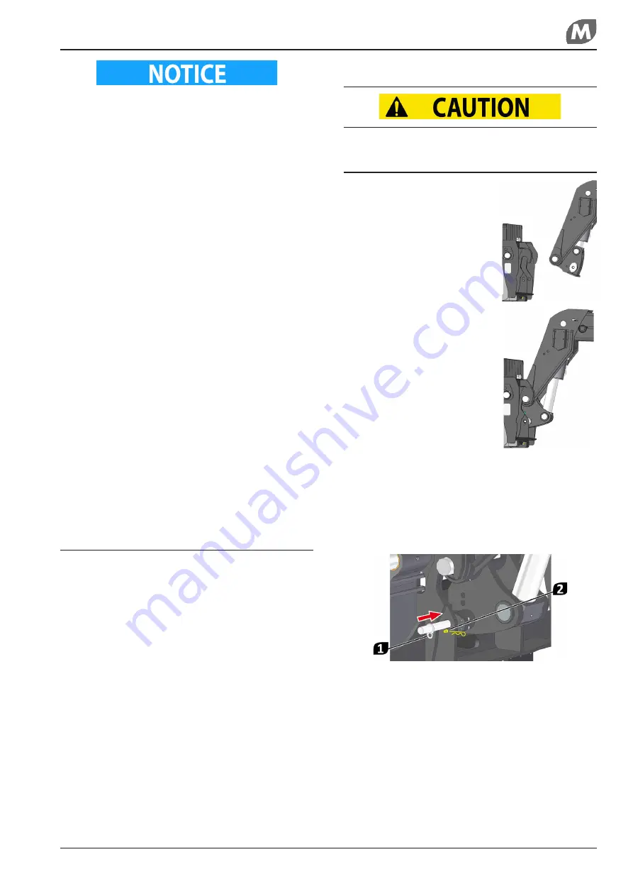
How to hook the equipment

Potential  risks  in  the  following  operations: 

crushing and injury to the upper limbs.

• 

position  the  equipment  on 


a stable level surface;

• 

bring  the  forklift  truck  near 

the  equipment,  positioning 

the  end  part  of  the  boom 

with  the  quick-fit  coupling 

retracted  suitably  to  fit  it  in 

the hooking seat;

• 

fit  the  equipment  with  the 

boom head quick-fit coupling;

• 

tilt  the  boom  head  coupling 

round  to  the  equipment 

frame to insert the shear pin;

• 

insert the retainer pin 

1

 into the hole present on 

the connecting flange of the boom aligned with the 

hole present on the equipment hooking structure;

• 

insert  the  split  shear  pin 

2

  in  the  hole  present 

on  the  pin  which  is  integral  with  the  equipment 

structure in such a manner as to prevent it from 

coming loose;

• 

connect  the  hydraulic  system  of  the  equipment 

to  the  connectors  on  the  head  of  the  vehicle’s 

telescopic boom [when present];

• 

connect  the  electrical  system  of  the  equipment 

to  the  connectors  on  the  head  of  the  vehicle’s 

telescopic boom [when present].

Vehicles produced by Magni T.H. are equipped with 

identification software that recognises the equipment 

connected and which enables movements and specific 

safety  systems  according  to  the  type  of  equipment 

connected.

Summary of Contents for W 8

Page 1: ...CTIONS Drafted in accordance with the essential requirement of health and safety 1 7 4 of Annex I to Directive 2006 42 CE Magni Telescopic Handlers Srl Via Magellano 22 41013 Castelfranco Emilia MO IT...

Page 2: ...Revision no Date Notes 0 07 2019 First edition A 09 2020 Added model W8 U 3L p n 52943...

Page 3: ...ption of the controls from the RTH cab 14 Description of the controls from the radio control 15 How to connect the radio control 16 Controls 16 TECHNICAL FEATURES AND LOAD CHARTS Winch W8 I P N 47917...

Page 4: ...pment safely This Manual contains all the information necessary for the user The operators must use the accessory for the purposes envisaged and identified in this Manual The information should be rea...

Page 5: ...rer and those envisaged by the legislation in force in the country concerned on matters of occupational safety replace worn components with genuine spare parts do not dump polluting material in the en...

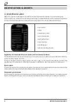
Page 6: ...ion plate and the functional stickers must be kept in good condition to ensure that all the data they contain are always legible over time If they are damaged and or no longer legible even only in par...

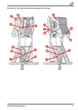
Page 7: ...IDENTIFICATION ELEMENTS 7 Position of the safety functional and generic stickers 5 1 2 4 9 2 3 2 6 2 7 8 7 6 2 7 8 10 11...

Page 8: ...horizontal levelling point 5 18259 Sticker indicating the anchor point 6 26739 Warning sticker with yellow diagonal stripes for the block 7 03439 Sticker indicating the greasing point 8 46538 Sticker...

Page 9: ...IDENTIFICATION ELEMENTS 9 EC declaration of conformity...

Page 10: ...equipment can result in serious accidents sometimes even mortal User obligations Read the Use and Maintenance Manual carefully Before using the equipment ensure its compatibility with the forklift tru...

Page 11: ...pment with hook inform the authorities responsible for inspections in your area Request the body responsible in the country of operation for yearly inspections How to hook the equipment Potential risk...

Page 12: ...it and of the receiver present at the head of the boom If there is no obvious damage please contact the Magni Telescopic Handlers Assistance Service If the RED button is pressed for safety reasons th...

Page 13: ...o sway small waves are formed in internal waters waves become moderately longer 6 39 49 25 31 10 8 13 8 Strong breeze larger tree branches moving whistling heard in telegraph wires whitecaps on the se...

Page 14: ...iption of the controls from the RTH cab B1 C1 C2 A2 A1 E1 E2 D1 D2 B2 A1 move the joystick forwards to lower the telescopic boom A2 move the joystick backwards to raise the telescopic boom B1 move the...

Page 15: ...radio control switch 11 emergency pump activation button 12 wiring connector socket for lifting platform Batteries In the centre of the radio control under the emergency button are the LEDs for check...

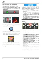
Page 16: ...tivate it as follows reset the red emergency button 2 by rotating it anticlockwise press the green radio control button once to reactivate the radio control forklift truck connection confirmed by the...

Reviews: