INSTRUCTIONS FOR USE AND WARNINGS
15
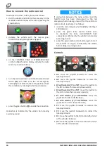
Description of the controls from the
radio control
1.
RPM switch: makes it possible to increase or decrease
the I.C. engine speed;
2.
emergency stop button: if pressed, it instantly stops
all movements;
3.
HARE/TORTOISE switch: changes the actuation speed
of the hydraulic commands given;
4.
RH joystick;
5.
OPT./SELECT
switch: changes the preset operating
programs for each accessory (if present);
6.
Load diagram indication LED: simulates the load
percentage applied to the accessory;
7.
TILT-OPTIONAL
switch: enables tilting of the accessory
or its specific functions;
8.
LH joystick;
9.
button to connect radio control → forklift truck;
10.
main radio control switch;
11.
emergency pump activation button;
12.
wiring connector socket for lifting platform.
Batteries
I
n the centre of the radio control under the emergency
button are the LEDs for checking operation of the radio
control and the charging state of the batteries.
13. green LED
:
•
not active indicates that the radio control is switched
off;
•
slow flashing indicates that the radio control is
switched on but is not connected to the vehicle;
•
fast flashing indicates that the radio control is
connected to the vehicle properly and is working.
14.
red LED
:
•
not active indicates the correct charging level of the
batteries;
•
on flashing indicates the low charging level of the
batteries;
•
on steady indicates a malfunction of the radio control.
To recharge the battery, remove it from the underside of
the radio control and insert it into the charger in the cab.


