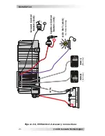
© 2015 Sensata Technologies
Setup
24
3.0 Setup
When the MMSA inverter/charger is not connected to a remote, the
internal DIP switches (Figure 1-4, Item 11) are used to determine
its operation.
Info:
When the MMSA is connected and networked with a
remote, the remote can be used to set up and/or control
the MMSA’s operation. Refer to your remote owner’s manual
for setup information.
3.1 Adjusting DIP Switch Settings
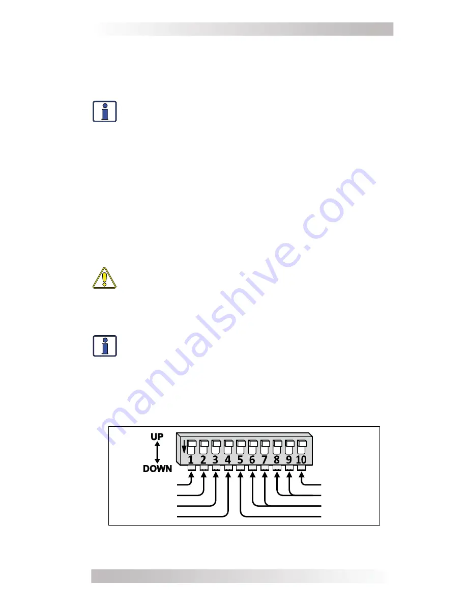
The DIP (Dual In-line Package) switch includes 10 individual slide
switches that can be set to the UP or DOWN position (Figure 3-1).
As a standalone inverter, the arrangement of the 10 switches
determines the MMSA’s operating parameters. The default setting
(all DIP switches UP) is adequate for most installations, however you
have the option to change some of the operating parameters. This
section shows how to set the DIP switch and provides information
on each switch setting’s function. Use the DIP switch adjustments
described below to con
fi
gure your MMSA1012 inverter/charger.
CAUTION:
The MMSA does not warn against or disallow
incorrect DIP switch settings. Ensure the settings used
to charge the batteries—the
Absorption Done Time
and
Battery Type
selections—are carefully checked against your
battery’s speci
fi
cations. Incorrect settings may damage the
battery or shorten battery life.
Info:
When changing any DIP switch setting, ensure each
switch is fully in the UP or DOWN position as needed. The
switch settings can be changed at any time, even while
the unit is operating. DIP switch changes become effective
when initiated, and do not require power to the MMSA to
be cycled on and off.
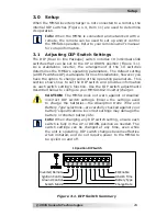
Figure 3-1, DIP Switch Summary
10 position DIP Switch
Ground Control
Ignition Control
Inverter/Remote
Battery Type
Absorb Time
EQ Enable
Search Mode
Charge Rate


