© 2015 Sensata Technologies
Setup
27
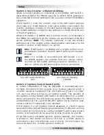
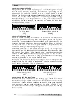
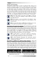
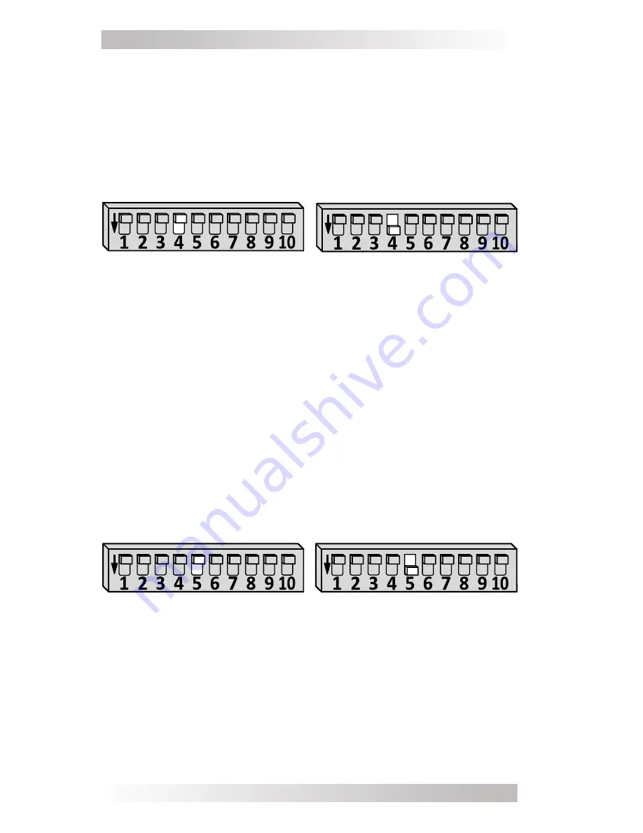
Switch 4: Search Mode
The position of DIP Switch 4 allows you to enable the power-saving
Search mode circuitry. Normally, the inverter is providing full AC
voltage to the loads (DIP Switch 4 is UP). When Switch 4 is set
DOWN, the Search mode feature is activated. When Search mode is
active, the inverter sends out pulses—consuming very little energy
from the battery—until the power level of the loads on the inverter
are above 5 watts, causing the inverter to “wake up” and start
providing full AC output.
Full AC Output
(UP)
Search Mode Activated
(DOWN)
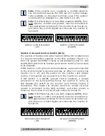
Switch 5: Charge Rate
The DIP Switch 5 setting determines the maximum current allowed
to charge the batteries during Bulk, Absorption, Float, and Equalize
charging. The two selections are provided as a percentage of the
inverter/charger’s maximum charging capability. Refer to the label
on the back side of the inverter (or Table 6-1) to determine the
inverter’s 100% (or maximum) charge rate.
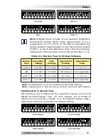
With DIP Switch 5 set UP (100% Charge Rate), the charger can
deliver 100% of the available charging capability of the inverter. With
DIP Switch 5 set DOWN (30% Charge Rate), the charge rate will be
limited to 30% of the maximum charging capability of the inverter.
This 30% setting is provided to help prevent battery overheating
caused by charging at too high a charge rate.
Example
: The maximum charge rate of your inverter/charger is 50
amps. When the DIP switch is set DOWN, the charge rate is limited
to 15 amps (15 amps = 30% of 50 amps)
.
100% Charge Rate
(UP)
30% Charge Rate
(DOWN)
Switches 6 & 7 Battery Type
Switches 6 & 7 are used to select the battery type—which determines
the battery charge pro
fi
le and ensures the batteries are receiving
the proper charge voltage. Select the battery type that matches
your system’s battery bank chemistry, or refer to Table 3-1 to
determine the speci
fi
c charge voltage to use based on the battery
type selected.


