Using a PT Controller: Troubleshooting
Page 123
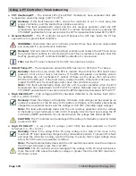
• FET
Overtemp-PT
– The internal FETs (Field Effect Transistors) have exceeded their safe
temperature operating range (
≥
85
˚
C/185
˚
F).
Remedy:
If this fault happens often, ensure the controller is not in a hot area, has
proper ventilation, and the cooling fans inside are working.
Note:
This fault automatically clears and the unit resumes operation when the FET
temperature has cooled down to 83°C/181°F or below. Manually clear by pressing the
PT’s RESET pushbutton for one second once the FET temperature falls below 85°C/185°F.
• Ground Fault-PT
– The PT controller turned off because the GFP fuse inside the PT has
opened due to a ground-fault condition.
WARNING:
Conductors that were normally grounded may have become ungrounded
and energized if a ground fault is indicated.
Remedy:
Find and correct the ground-fault condition and replace the GFP fuse. Once
the ground-fault condition is corrected and the GFP fuse is replaced, manually clear this
fault by pressing the PT controller’s RESET pushbutton for one second.
Info:
See the PT owner’s manual for the GFP fuse location and type.
• HiBatt
Temp-PT
– The temperature around the BTS has risen to 55°C/131°F or above.
Remedy:
Check the area where the BTS is located. Ensure that the BTS hasn’t been
placed in a hot area or near a hot device. If the BTS was placed on a battery ensure
the batteries are not overheated. If neither of these are the issue, then remove the
BTS from the BTS port. If the fault clears, replace the BTS. If the fault continues, then
inspect the BTS port for cleanliness and/or have the controller serviced.
Note:
This fault automatically clears and the unit resumes operation when the BTS
temperature has cooled down to 50°C/122°F or below. Manually clear by pressing the
PT’s RESET pushbutton for one second once the BTS temperature falls below 54°C/129°F
.
• High Bat VDC-PT
– High voltage (
≥
68 VDC) has been detected on the battery input termi-
nals (i.e., BAT+ to BAT-).
Remedy:
Check the voltage on the battery terminals. High voltage can be caused by an
incorrect connection of the PV array to the battery terminals, or the battery bank being
charged by an external means and the voltage is >68 VDC (including ripple voltage).
Note:
The fault automatically clears and the unit resumes operation once the voltage
to the battery input terminals is
≤
66.4 VDC. Manually clear the fault by pressing the PT
controller’s RESET pushbutton for one second when the voltage falls below 68 VDC.
CAUTION:
The PT controller can be damaged if the voltage to the battery input terminals
is above 68 VDC.
• High PV VDC-PT
– A very high PV voltage (>187 VDC) has been detected on the PV
terminals (i.e., PV+ to PV-).
Remedy:
Check if the sizing of the PV array voltage is too high or too close to the
maximum PT input operating voltage during cold weather periods. To prevent this fault
and keep the controller running, size the PV array to ensure the PV input voltage stays
below 187 VDC under any weather condition.
Note:
The fault automatically clears and the unit resumes operation once the voltage to
the PV input terminals is less than 187 VDC.
CAUTION:
The PT controller can be damaged if the voltage to the PV input terminals is
more than 200 VDC above the battery voltage or greater than the 240 VDC maximum,
whichever is less.

