© 2017 Sensata Technologies
26
WARNING:
In most electrical systems, the neutral-to-
ground bond is located in the main utility service entrance
panel. Remove any bond downstream from the inverter
to prevent multiple bonds. If there is an inverter sub-
panel—separate from a main electrical panel—it should
have a removable wire that allows the neutral bus to be
unbonded from the ground busbar.
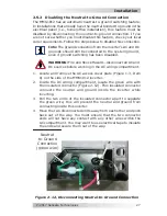
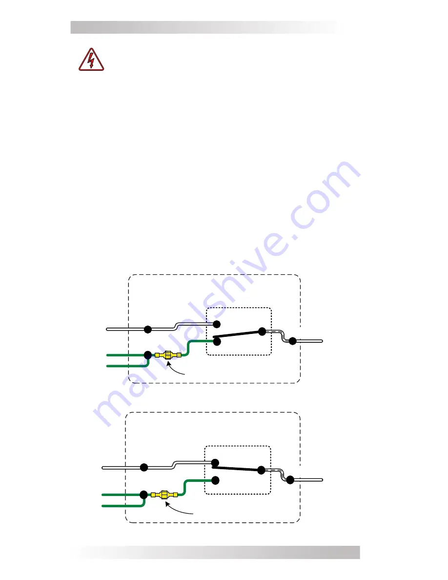
The MMS Series has automatic neutral-to-ground switching to
speci
fi
cally work in multiple source or mobile (i.e., truck/RV/boat)
applications. The MMS inverter/charger uses an internal relay that
automatically connects the AC neutral output terminal to the vehicle/
boat’s ground while inverting (Inverter mode) to provide the neutral-
to-ground bond; as shown in Figure 2-10. However, when an external
AC source (i.e., shorepower or a generator) is connected, another
neutral-to-ground connection is introduced in the system. When
the MMS1012 is connected to this external AC source and goes into
Standby mode, the internal relay automatically opens the neutral-
to-ground connection as shown in Figure 2-11. This design keeps
two neutral-to-ground connections from occurring at the same time,
thereby preventing an electrical shock hazard between the vehicle/
boat’s neutral and the external AC source’s neutral.
Figure 2-10, Neutral-to-Ground Connection (Inverter Mode)
Figure 2-11, Neutral-to-Ground Connection (Standby Mode)
Neutral
-to-Ground Connection
(inside AC compartment)
*
GROUND
Neu-Gnd Relay (K1)
NEU IN
Inside MMS Series Inverter /Charger
(Inverter Mode)
NEU OUT
Neutral
-to-Ground Connection
(inside AC compartment)
*
GROUND
Neu-Gnd Relay (K1)
NEU IN
Inside MMS Series Inverter /Charger
(Standby Mode)
NEU OUT
Installation


