background image

20

Make sure that the surface is clean and that 

no sharp objects can come into contact with 

or drop down onto the heating foil during 

the installation. Plan your work in a way 

that you don’t have to step directly on the 

heating foil.

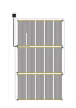
12.  Roll out the heating foil along the edge 

of the room. The copper can face either up 

or down. Make sure that the heating film is 

completely flat without any creases.

13. Cut the foil only along the perforation.

14. Cover the blind copper ends with a 50 x 

50 mm PVC tape.

15. Roll out the heating foil parallel to the 

first panel, they must not overlap.

16. Tape the foils to the insulation to avoid 

movements during the floor installation and 

service.

7. Connect the wires

Once the total floor surface is covered with 

the heating foil, the wires can be connected.

On the side where no connections are 

made, tape all the copper conductors with 

pieces of PVC tape (Pic. 13). Protect the 

heating foil with left over MAGNUM Isofoam 

PS insulation while you are working with 

connections. 

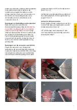
To protect the crimp connection

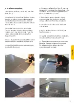
Make a 3x6 cm cut-out in the Isofoam just 

below the connection point (Pic. 6). Put a 

piece of PVC tape on the backside of the 

PS insulation. The crimp connection must 

not protrude above the surface of the PS 

Insulation to guarantee a good contact 

between the heating foil and the (wooden) 

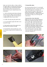
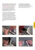
floor. Cut off 6mm of PVC insulation at 

the end of the cable, if only one cable is 

connected, fold the cable to fit into the 

connector crimp (Pic. 7). 

English

6

8

9

ATTENTION!
Always fold the cable double 
in case of single cable!

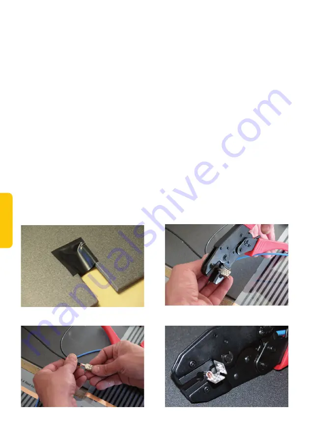
ATTENTION!
Always tighten the wires to the 
connector on both sides.

Summary of Contents for MAGNUM Foil

Page 1: ...MAGNUM Foil Installatievoorschriften Installation manual...

Page 2: ...kunt u van maandag t m vrijdag van 08 00 tot 17 00 uur bellen met de Supportline 0900 911 0 911 een e mail met uw vraag sturen naar info magnumheating nl of kijk voor meer info en andere producten op...

Page 3: ...st worden 11 De thermostaat dient in combinatie met de bijgeleverde vloersensor ge nstalleerd te worden 12 De maximale elektrische stroom per folieelement is 5 Amp re is max 15 strekkende meter folie...

Page 4: ...ect tegen de verwarmingsfolie komen te liggen De folie dient aangesloten te worden via een aardlek met een maximale weerstand van 30mA 5 Planning van de installatie Voordat begonnen wordt met het legg...

Page 5: ...eze aan op de positie van de kabelgoot indien de thermostaat wordt opgebouwd 6 Controleer de oppervlakte van de vloer Voor goed contact en om beschadigingen te voorkomen dient deze mooi vlak te zijn M...

Page 6: ...ppervlakte belegd is met verwarmingsfolie kunnen de voedingsdraden worden aangesloten U dient aan de zijde waar geen aansluitdraden worden aangesloten alle koperen geleiders af te plakken met stukjes...

Page 7: ...oedingsdraden lang genoeg zijn Bevestigen van de connector aan de folie Plaats de connector over de koperen geleider op de verwarmingsfolie Knijp de connector met de hand dicht foto 10 Knijp vervolgen...

Page 8: ...ets op de middenpagina en neem bij voorkeur een foto van de installatie 9 Bedekken van de Foil 1 Bedek de verwarmingsfolie met dampwerende PE folie met een minimale dikte van 0 1 mm foto 15 De folie d...

Page 9: ...daard DIN formaten Controleer of de stroom is afgesloten HEATING N Aansluitdraad verwarmingskabel N Stroomtoevoer Neutraal L Stroomtoevoer Fase HEATING L Aansluitdraad verwarmingskabel FLOOR SENSOR Aa...

Page 10: ...i n s t r u c t i o n s b e f o r e i n s t a l l a t i o n I P X 1 1 0 0 W a t t m 2 M A X 5 A m p s D i r e c t f l o o r h e a t i n g f i l m f o r d r y l o c a t i o n s R e a d i n s t r u c t...

Page 11: ...GNUM Foil ________W m Totale lengte folie ge nstalleerd ________Mtr Gemeten weerstandswaarde totale installatie ________Ohm Controle berekening W m x 0 6 x meterlengte totaal wattage systeem _____W m...

Page 12: ...12 Schets of foto s van installatie...

Page 13: ...13 Schedule or pictures of the installation...

Page 14: ...d MAGNUM Foil _______ W m2 Total length foil installed _______ Meter Measured resistant value total installation _______ Ohm Control Check calculation W m2 x 0 6 x meter length total Watts system ____...

Page 15: ...i n s t r u c t i o n s b e f o r e i n s t a l l a t i o n I P X 1 1 0 0 W a t t m 2 M A X 5 A m p s D i r e c t f l o o r h e a t i n g f i l m f o r d r y l o c a t i o n s R e a d i n s t r u c t...

Page 16: ...ensure that you have the correct tools and materials The electrical installation must be carried out by a qualified electrician in accordance with IEE Regulations Visit our website for your local MAGN...

Page 17: ...ls should never be placed on a floor with electrical heating 11 The thermostat needs to have the floor sensor properly installed to work 12 The maximum current distributed through each length of heati...

Page 18: ...come in contact with the heating foil The heating foil must be installed together with a Residual Current Device RCD with a maximum breaking current of 30mA 5 Installation Planning Before installing...

Page 19: ...ied with the system 5 Install the flexible conduit with a smooth bend at the floor level 6 Check the surface of the floor To prevent damage it is important that the surface is flat and clean The maxim...

Page 20: ...the total floor surface is covered with the heating foil the wires can be connected On the side where no connections are made tape all the copper conductors with pieces of PVC tape Pic 13 Protect the...

Page 21: ...set max gap 1 3mm Place the crimp over the copper band on the heating film Tighten the crimp by hand Pic 10 Then tighten the crimp with the crimp tool in a 45 degree angle from both sides Pic 11 and 1...

Page 22: ...9 Cover the Foil 1 Cover the Foil with age resistant PE foil with a minimum thickness of 0 1 mm Film must overlap 200 mm if it is necessary to use several sheets to cover the surface Pic 15 2 Install...

Page 23: ...ostat HEATING N Heating Cable connection N N Power connection Neutral L Power connection Live HEATING L Heating Cable connection L FLOOR SENSOR Floor sensor connections When connecting the power suppl...

Page 24: ...24 MAGNUM Heating B V Stevinweg 8 4691SM Tholen T 31 0 166 609 300 E info magnumheating nl W magnumheating nl v0121...

Reviews: