8
ASSEMBLY INSTRUCTION:
STEP 1-1.
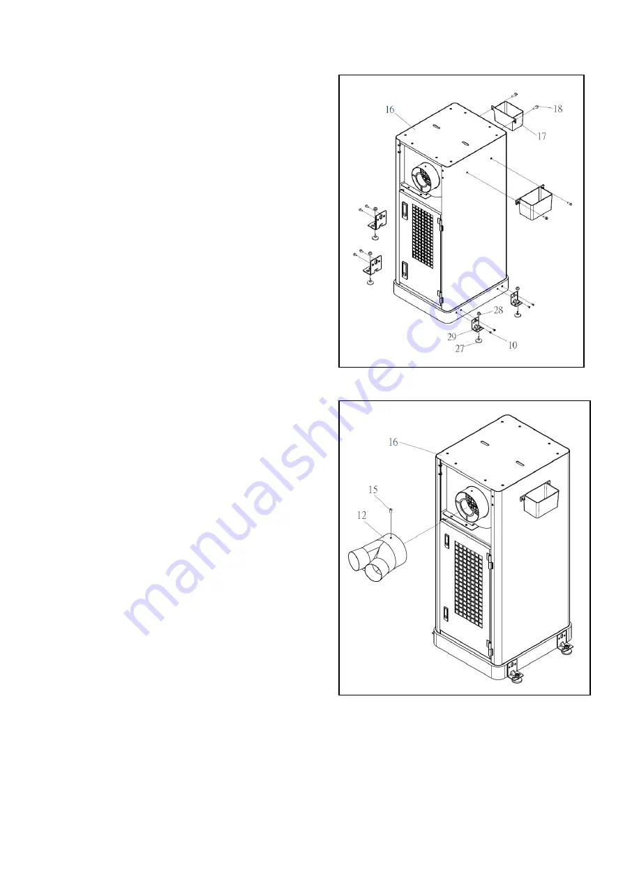
Assemble the fixing pad (NO. 29) on the main body
(NO. 16) with hex flange screw (NO. 10).
STEP 1-2.
Tight the foot pad (NO. 27) with the fixing pad
(NO. 29) by using nut with cap
(NO. 28).
STEP 1-3.
Tight the tray (NO. 17) on the main body (NO. 16)
with hex flange screw (NO. 18).
See Fig. 1
(Fig.1)
STEP 2-1
Assemble the inlet adaptor (NO. 12) on the main body
(NO. 16) with phillips head screw
(NO. 15).
See Fig. 2
(Fig.2)


