background image

11

ADJUSTMENTS  

ADJUSTING KNOB 

TABLE 

90

Shaft for 90

°

Summary of Contents for MI-91600

Page 1: ...MODEL NO MI 91600 OPERATING MANUAL...

Page 2: ...switches or by removing starter keys 9 DON T FORCE TOOL it will do the job better and safer at the rate for which it was not designed 10 USE RIGHT TOOL Don t force tool or attachment to do a job for...

Page 3: ...epaired or replaced 22 DIRECTION OF FEED Feed work into a blade or cutter against the direction of rotation of the blade or cutter only 23 NEVER LEAVE TOOL RUNNING UNATTENDED TURN POWER OFF Don t leav...

Page 4: ...the OFF position and the power cord disconnected 20 Do not remove jammed cutoff pieces until blade has stopped GROUNDING INSTRUCTIONS 1 All grounded cord connected tools In the event of a malfunction...

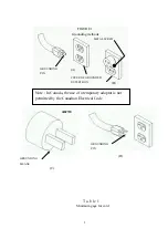
Page 5: ...ich looks like the adapter illustrated in Sketches B and C may be used to connect this plug to a 2 pole receptacle as shown in Sketch B if a properly grounded outlet is not available The temporary ada...

Page 6: ...A METAL SCREW COVER OF GROUNDED OUTLET BOX GROUNDING PIN Note In Canada the use of a temporary adaptor is not permitted by the Canadian Electrical Code GROUNDING PIN GROUNDING MEANS ADAPTER D C T a b...

Page 7: ...Total length of cord in feet Ampere Rating 120V 240V 25ft 50ft 100ft 150ft 50ft 100ft 200ft 300ft Not More More Than Than AWG 0 6 6 10 10 12 12 16 18 16 16 14 18 16 14 12 16 16 14 12 14 12 Not Recomme...

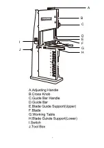
Page 8: ...7 A B C D E F G H J I...

Page 9: ...er blade support The blade support bearing A should be adjusted so it almost touches the back of the saw blade when the blade is tracking properly To adjust loosen indexable locking lever B and slide...

Page 10: ...so it almost touches the back of the saw blade To adjust loosen hex screw B and slide bracket in or out until the adjustment is correct Tighten screw The blade guide bearings C should be adjusted so...

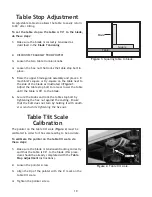
Page 11: ...Secure the knobs and lock the table stop bolt by tightening the hex nut against the casting Ensure that the bolt does not turn by holding it with anoth er wrench while tightening the hex nut Table St...

Page 12: ...iter slot as indicated by positions A and B in Figure 3 6 Adjust the table until the distance between the blade and miter slot is equal at both ends 7 Tighten the trunnion bolts Table Alignment A B Mi...

Page 13: ...nd twist it rightside out 7 Slip the blade through the guides and mount it over the upper and lower wheels 8 Apply tension 9 Turn the tension knob until proper blade tension has been reached according...

Page 14: ...rst ensuring that it touches both the top and bottom rim then adjust the upper wheel tracking knob to make the upper wheel parallel with the lower wheel If the straightedge does not touch both wheels...

Page 15: ...not make the wheels coplanar with the tracking knob or by shimming the upper wheel Make sure the upper wheel is adjusted as close as possible to being coplanar with the lower wheel before beginning Do...

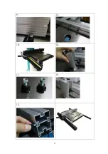
Page 16: ...INSTALL 1 5 2 6 3 7 4 8 14...

Page 17: ...9 13 10 14 11 15 12 15...

Page 18: ...11 ADJUSTMENTS ADJUSTING KNOB TABLE 90 Shaft for 90...

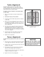
Page 19: ...ng brackets to the table and raise or lower the front rails along the elongated holes in the mounting brackets Level the fence front and back as needed and set the spacing between the bottom of the fe...

Page 20: ...ing the power wires make sure the voltage between the machine and your factory power source is the same 2 Take out the electrical cover at the electrical control box outside 3 Connect the power wires...

Page 21: ...circuit 4 Refer to motor nameplate for correct voltage Motor overheats 1 Motor overloaded 2 Air circulation through the motor restricted 1 Reduce load on motor 2 Clean out fan and fan cover Machine sl...

Page 22: ......

Page 23: ...161...

Page 24: ...14...

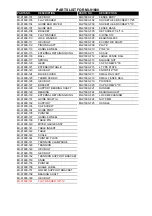
Page 25: ...UT MI 91600 68 PHILLIPS FLAT HEAD SCREW MI 91600 19 LOWER WHEEL MI 91600 69 FLAT WASHER MI 91600 21 SHAFT MI 91600 70 HEX NUT MI 91600 22 LOCK NUT MI 91600 71 INTERNAL RETAINING RING MI 91600 23A BEAR...

Page 26: ...EX BOLT MI 91600 F16 KNOB 5 16 5 8 MI 91600 124 BLADE COVER MI 91600 F17 SMALL RAIL CAP MI 91600 125 THUMB SCREW MI 91600 F18 SMALL FENCE RAIL MI 91600 126 HEX BOLT MI 91600 F19 POINTER MI 91600 127 B...

Page 27: ......

Reviews: