-8-
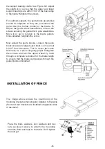
the support bearing shafts. See Figure 8-3. Adjust
the shafts in or out so that the upper and lower
support bearings are within 1/64” of the back edge
of the blade. Retighten the screws.
For optimum support, the guide block assemblies
should be adjusted so they are just behind the
gullet line (the hollow points) of the blade. To
adjust the guide block assemblies, loosen the
screws securing the guide block yoke assemblies.
Move in or out in relation to the blade gullets.
Once adjusted, retighten the screw.
Now adjust the guide blocks. Loosen the guide
block screws and adjust each block so it is about
0.004” from the blade. This is about the same
thickness as a piece of typing paper. Retighten
the screws and turn the upper wheel by hand
through a complete revolution for the blade length
to ensure that the blade weld passes through the
guide blocks unhindered.
INSTALLATION OF FENCE
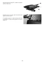
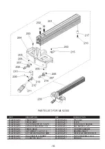
The image above shows the positioning of the
mounting brackets when properly installed to the table
(front and rear brackets are installed at opposite sides
of the table).
Place the bolts, washers, lock washers and hex
nuts as shown above to attach the mounting
brackets (front and rear) to the table. Don’t tighten
the nuts yet.
Summary of Contents for MI-92300
Page 1: ...MODEL NO MI 92300 OPERATING MANUAL START STOP ON OFF...
Page 15: ...14...
Page 17: ......
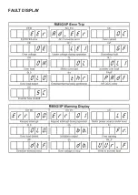
Page 20: ...FAULT DISPLAY...


