Advanced Troubleshooting
312004B
23
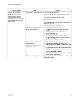
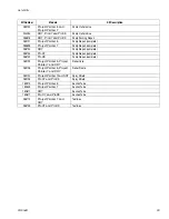
Sprayer Wiring Problems
NOTE:
Remove enclosure
mounting screws and pull
enclosure away from drive
housing. Take care not to pull on
leads from electrical cord and
power switch.
Sprayer electrical cord damaged.
Unplug sprayer electrical cord.
Disconnect black electrical cord wire at power switch.
Unplug in-line connection white cord wire.
Plug in electrical cord.
Test voltage between black and white wires. Meter must
read 85 to 130V AC.
Replace electrical cord if no voltage.
SR7, ProX7 and ProX9 - Sprayer
power switch damaged.
1.
Unplug sprayer electrical cord.
2.
Disconnect black control board wire at power
switch.
3.
Unplug in-line connection white cord wire.
4.
Plug in electrical cord.
5.
Turn power switch ON.
6.
Test voltage between open terminal of power
switch and white electrical cord wire. Meter must
read 85 to 130V AC.
7.
Replace power switch if no voltage.
Motor thermal overload cutoff
switch damaged.
Startup Hazard After Thermal
Overload
, page 5.
1.
Unplug sprayer electrical cord.
2.
Remove motor harness from control card.
3.
Check for continuity between yellow leads or motor
harness.
4.
If thermal relief switch is open (no continuity) allow
motor to cool.
5.
If switch remains open after motor cools, replace
motor using
Motor Kit
, page 28.
6.
If thermal relief switch closes after motor cools, find
correct cause of overheating.
Terminals are damaged or loose.
Replace any damaged terminals. Make sure all terminal
connections are tight.
Specific Problem
Cause
Solution
Summary of Contents for 261800
Page 35: ...Notes 312004B 35 Notes ...
Page 39: ...Notes 312004B 39 Notes ...
Page 45: ...Notes 312004B 45 Notes ...


