309044
19
Motor Kit
XR Motor/Drive Housing Replacement Kit 243236
If
Motor Diagnostics
(page 16) reveal a damaged motor, or if either of the motor brushes are shorter than 1/4 in.
(6.4 mm), or if the motor shaft cannot turn, replace the motor as follows:
Disassembly
See
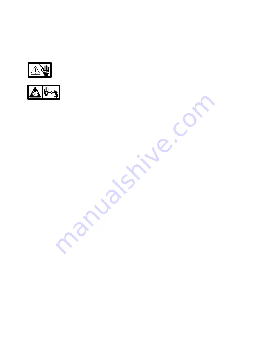
Electric Shock Hazard
on
page 7.
See
Pressure Relief
Procedure
on page 6.
1.
Unplug electrical cord, and relieve pressure.
2.
Remove the four cover screws and front cover.
3.
Remove yoke and guide rods.
4.
Disconnect pressure control harness from control
board connector at back of drive housing.
Using
fingernail or tip of small, flat-blade screwdriv-
er, press tab on right side of connector to
release.
5.
Remove pump and the two mounting pins from
drive housing.
6.
Remove gear.
7.
Remove enclosure mounting screws from both
side enclosures. Fully remove left enclosure from
sprayer. Pull right enclosure away from drive
housing.
Take care to not pull on the leads from
the electrical cord and the Power switch (B).
8.
Disconnect motor harness from back of control
board.
9.
Remove screw that mounts control board, and
remove control board from drive housing.
10. Carefully pull 3-legged fan brace from pegs on fan
shield. Use rag or glove to protect your fingers,
and pull fan off motor shaft.
11. Pull fan shield from motor.
Note how the motor
leads are routed through the arches and slots
of the fan shield.
12. Remove stand (XR5) or cart (XR7 or XR9) legs
from drive housing.
Installation
D
Read all
Installation Notes
in service drawing on
facing page.
D
To prevent misalignment, assemble sprayer tipped
onto back of enclosure.
1.
Install stand (XR5) or cart (XR7 or XR9) legs on
new drive housing.
2.
Carefully route the motor leads as you observed
them in Step 11 of
Disassembly
(yellow wires
above black wire).
3.
Install new fan shield on new motor. Orient tab
and “TOP” to top of fan shield.
4.
Install new fan on motor shaft.
5.
Install shaft bushing on new motor shaft, and
install new 3-legged fan brace in pegs on fan
shield.
6.
Install control board on new drive housing, and
tighten control board mounting screw. See
Control
Board Detail
on facing page.
7.
Plug new motor harness into back of control board.
8.
Reinstall enclosures on sprayer, and install and
tighten enclosure mounting screws.
9.
Install gear in new drive housing so teeth engage
with drive pinion of motor.
10. Route pressure control harness behind pump
through retention clip, and connect to control board
connector at back of drive housing (connect with
tab to the right).
11. Install pump on mounting pins.
Make sure the
plastic washers are between the drive housing
and the pump.
12. Install yoke with rod cap in slot of yoke, as shown
in
Rod/Yoke Detail
on facing page.
13. Check final assembly against
Drive Train Detail
on facing page.
14. Install front cover and cover screws.


