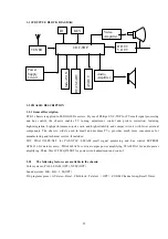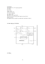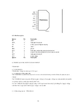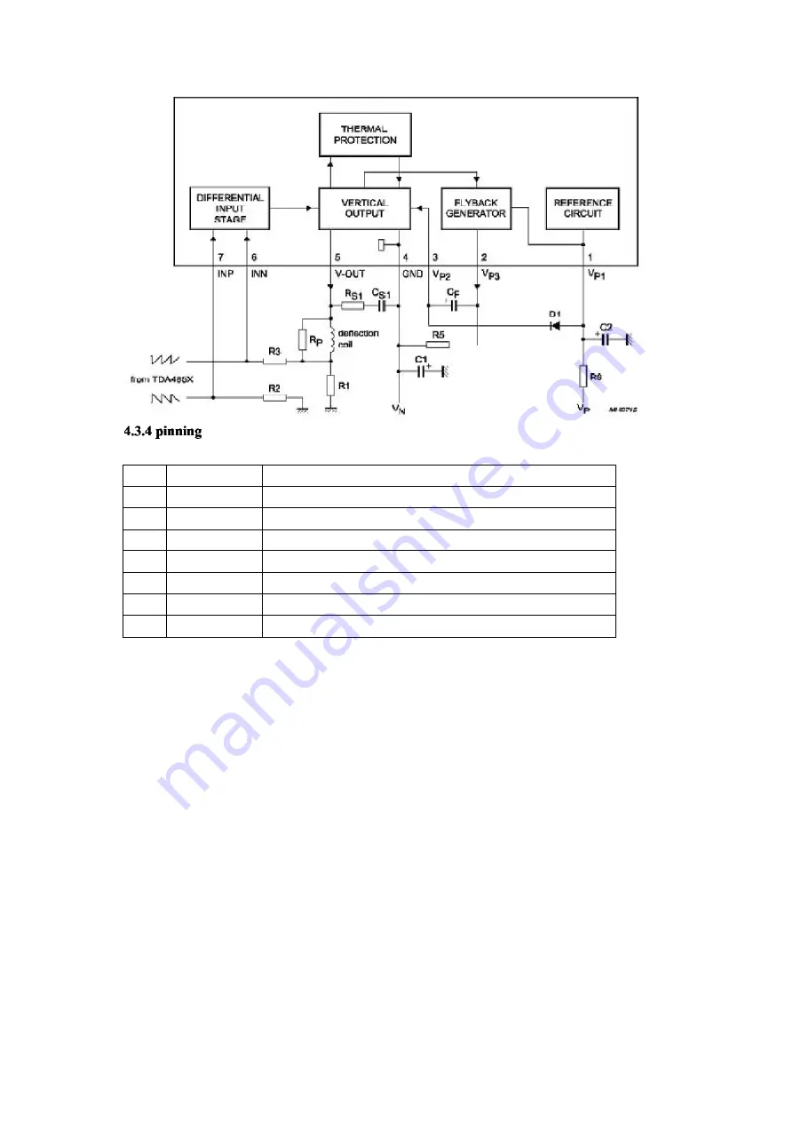
PIN SYMBOL
DESCRIPTION
1
VP1
positive supply voltage 1
2
VP3
flyback generator output
3
VP2
supply voltage 2 for vertical output
4
GND
ground or negative supply voltage
5 V-OUT
vertical
output
6
INN
inverted input of differential input stage
7
INP
non-inverted input of differential input stage
4.4 EEPROM AT24C16
4.4.1 Features
Data EEPROM internally organized as 1024/2048 bytes and 64/128 pages×16 bytes
Page protection mode, flexible page-by-page hardware write protection -Additional protection EEPROM of
64/128 bits, bit per data page 1-Protection setting for each data page by writing its protection bit -Protection
management without switching WP pin
Low power CMOS
Vcc=2.7 to 5.5V operation
Two wire serial interface bus, IIC-Bus compatible
Filtered inputs for noise suppression with Schmitt trigger
Clock frequency up to 400 kHz
High programming flexibility
−
Internal programming voltage
−
Self timed programming cycle including erase
−
Byte-write and page-write programming, between 1 and 16 bytes
17
Summary of Contents for PF21500
Page 20: ...李 庆亮 10 11 19 15 06 ...

