background image

separation in all poles of at least 3 mm.

9. If the supply cord is damaged, it must be replaced 

by the manufacturer, its service agent or similarly 

qualified persons in order to avoid a hazard.

WARNING: This heater is not equipped with a device 

to control the room temperature. Do not use this 

heater in small rooms when they are occupied by 

persons not capable of leaving the room on their 

own, unless constant supervision is provided.

2. Mounting

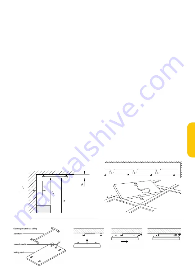
2.1 Integrated in ceiling, put in exposed grid (See fig 

A and B)

1. Place the cassette in the required ceiling square. 

Minimum design height ”H” for dismounting, T-profile 

32x15: 150 mm, T-profile 38x24: 200 mm. NOTE! Avoid 

fixing vertical bars in the T-profile where a heating 

panel is to be installed. The panel fills out the whole 

square.

2. Connect the panel.

3. The last page in this mounting instruction is to be 

filled out and fixed adjacent to the distribution board 

and it has to contain (drawing) the locations of the 

heating units. 

2.2 Bracket mounting (See fig A and C)

1. When mounting in gypsum board, make sure that 

the panel frame is anchored in the beam behind. 

During long-term high temperatures the strength of 

the board is reduced. 

2. Measure, drill and screw the panel frame to the 

ceiling. 

3. Hook the panel brackets to the panel frame on the 

ceiling 

4. Connect the panel.

3. Scedule or pictures of the installation

The Middle page in this mounting instruction is to 

be filled out and fixed adjacent to the distribution 

board and it has to contain (pictures or drawing) the 

locations of the heating units distribution board and 

it has to contain (pictures or drawing) the locations of 

the heating units.

False ceiling


Min.distance 

[mm]

Ceiling

80

Wall, long side of the unit

50

Wall, short side of the unit

50

Obstacle

500

Floor

1800

Fig. 1: Minimum mounting distance

Minimum mounting distance

Mounting

Min  1,5 mm²

Max 2100 W

Fig. 3

A

B

C

D

E

Fig. 1

Fig. 2

Fig A  

Minimum distance

A: Ceiling  80mm 

C: Obstacle   500mm

B: Wall 

50mm 

D: Floor     1800mm

Fig B  

Integrated in ceiling

Fig C  

Bracket mounting

Mounting

Min  1,5 mm²

Max 2100 W

Fig. 3

A

B

C

D

E

Fig. 1

Fig. 2

MAGNUM Sol

7

English

Summary of Contents for Sol 300

Page 1: ...MAGNUM Sol Installatievoorschriften Installation manual ...

Page 2: ...sche installatie van de panelen mag uitsluitend worden uitgevoerd door een erkend installateur Gedurende de installatie dient de stroomtoevoer afgesloten te blijven Aansluiting dient via een aardlekschakelaar te geschieden volgens geldende installatienormen 30mA Minimale installatiehoogte is 1 8 meter kleinste afstand tot een muur minimaal 50mm fig 1 De aansluitkabel dient een minimale doorsnede t...

Page 3: ...2 Montage d m v frame fig A C Bij montage aan plafond met gipsplaten Zorg dat de beugel bevestigd wordt aan de constuctiebalken van het plafond Door langdurige warmte kan de sterkte van het gipsboard afnemen Meet boor en schroef het frame vast aan het plafond Haak het paneel aan het frame Sluit het paneel aan 3 Schets of foto s van de installatie Als laatste dient u een schets of foto s van de ins...

Page 4: ...MAGNUM Sol 4 Foto s of tekeningen van de installatie Pictures or drawings of the installation ...

Page 5: ...MAGNUM Sol 5 ...

Page 6: ...ersions with a cord and plug 2 Mounting height above floor shall be at least 1 8 m lateral distance to wall shall be at least 50 mm See fig 1 3 One or more units have to be connected to power line with a differential circuit breaker rated at 30 mA The cable section has to be at least 1 5 mm2 4 Units with cable and plug can be interconnected using appropriate connection materials 5 The maximum powe...

Page 7: ... locations of the heating units 2 2 Bracket mounting See fig A and C 1 When mounting in gypsum board make sure that the panel frame is anchored in the beam behind During long term high temperatures the strength of the board is reduced 2 Measure drill and screw the panel frame to the ceiling 3 Hook the panel brackets to the panel frame on the ceiling 4 Connect the panel 3 Scedule or pictures of the...

Page 8: ...C F Technics MAGNUM Heating B V Slabbecoornweg 41 4691RZ Tholen T 31 0 166 609 300 F 31 0 166 604 877 E info magnumheating nl W magnumheating nl v0116 ...

Reviews: