Revision 001
ix
Model TE100
Electronic Small Bagging Scale
List of Figures
Figure
Page
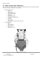
Figure 1-1. TE100 Front View ...........................................................................................................1-2
Figure 1-2. Scale Cabinet and Shut Off Gate ...................................................................................... 1-3
Figure 1-3. Load Cell .........................................................................................................................1-4
Figure 1-4. MAC Valves ....................................................................................................................1-5
Figure 1-5. MAC Valve Flow Adjustment.......................................................................................... 1-5
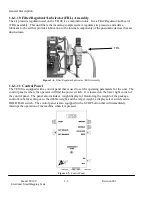
Figure 1-6. Filter/Regulator/Lubricator (FRL) Assembly....................................................................1-6
Figure 1-7. Control Panel ...................................................................................................................1-6
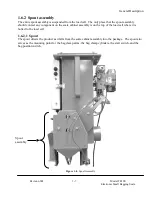
Figure 1-8. Spout Assembly ...............................................................................................................1-7
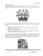
Figure 1-9. Chain Links and Pivot Block............................................................................................1-8
Figure 1-10. Bag Clamp Arm – Shown With Stainless Steel Deflector ...............................................1-8
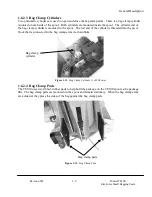
Figure 1-11. Bag Clamp Cylinder (1 of 2 Shown)...............................................................................1-9
Figure 1-12. Bag Clamp Pads .............................................................................................................1-9
Figure 1-13. Start Switch.................................................................................................................. 1-10
Figure 1-14. Bag Position Switch ..................................................................................................... 1-10
Figure 1-15. TE100 With Small Bag Adapter Installed..................................................................... 1-11
Figure 2-1. Typical Shipping Box (2 Boxes Shown)...........................................................................2-1
Figure 3-1. Mounting the TE100 ........................................................................................................3-1
Figure 3-2. Hanging the Cabinet Assembly on the Hopper Flange ......................................................3-2
Figure 3-3. Shipping Bracket Location ...............................................................................................3-2
Figure 3-4. MAC Valve Connections And Schematic.........................................................................3-3
Figure 3-5. Load Cell Connections .....................................................................................................3-4
Figure 3-6. Lubricator – Oil Flow Control..........................................................................................3-4
Figure 3-7. Control Panel ...................................................................................................................3-6
Figure 3-8. Relay Board .....................................................................................................................3-7
Figure 3-9. Relay Board Schematic ....................................................................................................3-7
Figure 3-10. Decimal Point Switches..................................................................................................3-9
Figure 3-11. Display Trim Pot.......................................................................................................... 3-10
Figure 3-12. ZERO Knob And Lock Collar ...................................................................................... 3-10
Figure 3-13. Coarse Zero Adjustment............................................................................................... 3-11
Figure 3-14. Hanging A Certified Test Weight On The TE100 ......................................................... 3-11
Figure 3-15. Weight Trim Potentiometer .......................................................................................... 3-12
Figure 3-16. Coarse Weight Gain Switches ...................................................................................... 3-12
Figure 3-17. Density Correction Switch............................................................................................ 3-14
Figure 3-18. Over/Under Reject Controls ......................................................................................... 3-15
Figure 3-19. Dribble Gate Cylinder Mounting .................................................................................. 3-16
Figure 4-1. Control Panel ...................................................................................................................4-2
Figure 4-2. Over/Under Reject Controls .............................................................................................4-4
Figure 7-1. Pivot Block Setscrew Location (Setscrew Uninstalled Here) ............................................7-1
Figure 7-2. Shut Off Gate Adjustment ................................................................................................7-2
Figure 7-3. Adjusting Airflow From The MAC Valve ........................................................................7-3
Figure 7-4. Spout Mounting Bolts ......................................................................................................7-5
Summary of Contents for TE100
Page 1: ...Taylor Products Model TE100 Electronic Small Bagging Scale Operation and Maintenance Manual ...
Page 6: ...Model TE100 Electronic Small Bagging Scale iv Revision 001 This Page Intentionally Left Blank ...
Page 86: ......
Page 88: ......
Page 90: ......
Page 91: ...Machine Type TE100 Dwg Name ISO 4 dwg Dwg View Scale Cabinet Exploded View ...
Page 92: ......
Page 95: ...Machine Type TE100 Dwg Name ECT146ASY dwg Dwg View Controller Circuit Board ...


