


q
Engine Bolts and Firewall Requirements
The engine should be mounted to a glass filled nylon mount or an inte-
grated hardwood beam mount. Use only high quality steel cap screws and
related hardware to mount the engine to the motor mount. The firewall in
the airplane should be aircraft grade 5-ply plywood and be no less than
1/4” thick. The firewall should also be reinforced to meet the torque and
weight of the engine.
q
Muffler Installation
The muffler is mounted to the engine using the two socket cap screws, two
split washers and one of the two gaskets provided. The second gasket
should be kept as a spare. Tighten
both screws securely to prevent the
muffler from loosening during
flight. The exhaust cone on the rear
half of the muffler is adjustable to
better match the installation of your
particular application. To adjust the
cone, loosen the retaining nut us-
ing a small wrench. Rotate the cone
to the desired angle then tighten the retaining nut completely while hold-
ing the thru bolt in place, from the front of the muffler, using a flat blade
screwdriver. It is important to tighten the retaining nut completely to pre-
vent the cone from rotating during flight.
q
Tank Size and Orientation to Carburetor
Ideally the stopper in the fuel tank should be even with the high speed
needle valve or just slightly below the high speed needle valve. Most
models will only allow the fuel tank to be mounted higher than the ideal
location. A fuel tank that is positioned higher than the ideal location usu-
ally doesn’t pose any problem except when it is mounted excessively higher
and/or used in conjunction with an inverted mounted engine or during ex-
treme aerobatic flight. If mounting your engine inverted it is advised to
lower the fuel tank so the stopper is slightly below the high speed needle
valve. Doing this will prevent fuel from siphoning into the engine and
flooding it when the fuel tank is full. If you cannot lower the fuel tank far
enough, we suggest lowering it as far as can be allowed in your particular
application.
The size of the fuel tank used for the .25 or .28 should be 6oz. - 8oz.
depending on the model and the length of flights desired. Use of an 8oz.
tank will provide about 15 minutes of run time at full throttle. Use of a fuel
tank any larger than 8oz. can lead to excessive leaning of the engine mix-
ture during flight and is not recommended.
The Size of the tank used for the .32 - .36 should be 8oz. - 10oz. Use
of a 10oz. tank will provide about 20 minutes of run time at full throttle.
Use of a tank any larger than 10oz. can lead to excessive leaning of the
engine mixture during flight and is not recommended.
q
Carburetor Installation
The carburetor is held in place using two machine screws. Slide the base
of the carburetor into the crankcase,
being careful to keep the carbure-
tor perpendicular to the front of the
engine. With your thumb, push
down on the carburetor firmly so
the base of the carburetor sets com-
pletely into the crankcase and the
carburetor o-ring seals the gap be-
tween the crankcase and carbure-
tor. While holding the carburetor in place, thread one machine screw into
each side of the carburetor. Use a screwdriver to carefully tighten both
screws securely. There is no need to overtighten the screws.
Note: Do not overtighten the retaining screws. The screws only
need to be tightened enough to keep the carburetor from moving in the
crankcase. Overtightening the screws can cause severe damage to the
base of the carburetor.
q
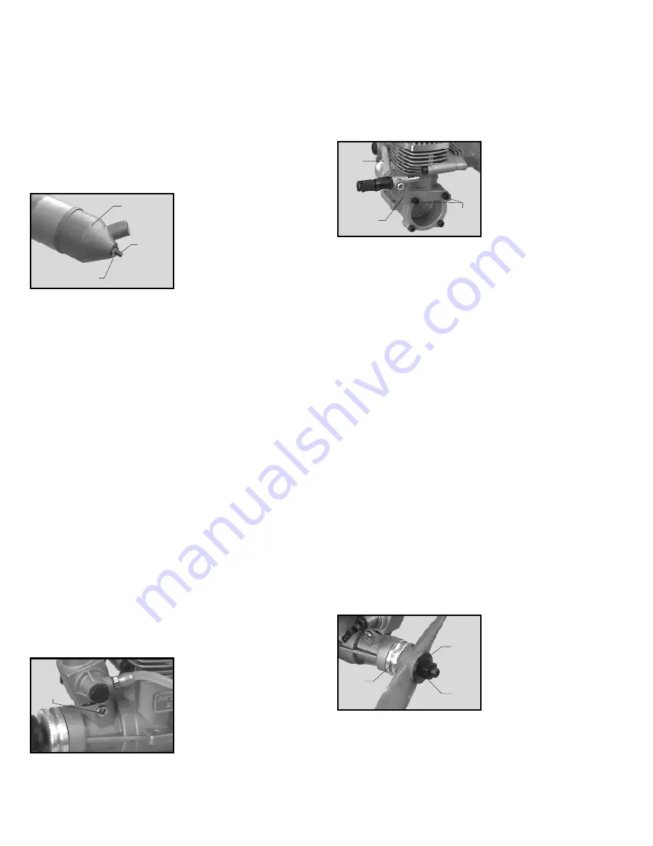
Rear Needle Valve Installation
The rear needle valve assembly is held in place using the two socket cap
screws and two split washers pro-
vided with the assembly. To mount
the assembly, remove the two up-
per backplate screws, set the as-
sembly in place, then install the two
screws and split washers provided
with the assembly. Tighten the
screws completely. Install the pro-
vided length of silicon fuel line
between the needle valve assembly and the carburetor. The fuel pickup
line from your fuel tank will connect to the larger brass nipple on the needle
valve assembly.
q
Needle Valve Extension
If an extension is required to adjust the high speed needle valve, use a
1.5mm diameter wire of the necessary length. Loosen the set screw in
the side of the needle valve, insert the wire into the end of the needle
valve and tighten the set screw firmly. If the extension is more than 3”
long we recommend supporting the outer end of the extension to prevent
excessive vibration.
q
Idle Stop Screw and Rotor Bolt
The rotor bolt holds the throttle barrel into the carburetor body on all four
of these engines. These bolts typically do not require any adjustment. On
the .25ARNV and the .28ARNV, the idle stop screw adjusts the closure of
the throttle barrel. We recommend that the throttle barrel be allowed to
close completely so the engine can be shut off using your radio transmit-
ter. Turning the screw clockwise will cause the barrel to stay open more.
Turning the screw counterclockwise will allow the barrel to close more.
Do not turn the screw any further out than necessary to allow the throttle
barrel to fully close. The .32ARNV and .36ARNV does not utilize an idle
stop screw. Barrel closure is controlled completely by the transmitter.
q
Propeller Installation
Note: Before installing any propeller it must be properly balanced.
Running an engine using an improperly balanced propeller can lead to ex-
cessive vibration, which can cause excessive stress and wear on both the
engine and the airframe. Balance the propeller using the recommended
method of the propeller manufacturer. Several products are available to
properly balance propellers. Ask your local retailer for more information
about these items.
Using a 1/4” drill bit or a prop
reamer, drill out the hole in the pro-
peller hub to fit the crankshaft. The
crankshaft is 1/4” in diameter.
Slide the propeller onto the crank-
shaft, up against the thrust washer.
Slide the propeller washer up
against the propeller. Thread the
prop nut onto the crankshaft. Com-
pletely tighten the prop nut to secure the propeller in place. When tighten-
ing the prop nut, use the proper size open end wrench. Do not use pliers.
Note: If you are installing a spinner onto your engine the cone of
the spinner must not rub against the propeller. If the spinner cone rubs
against the propeller this could lead to propeller damage and eventual
propeller failure.
Exhaust
Cone
Thru Bolt
Retaining Nut
Machine
Screw
Mounting
Bracket
Socket
Cap
Screws
Fuel
Line
Thrust
Washer
Prop
Washer
Prop
Nut


