


XL .52RFS AIRCRAFT ENGINE MAINTENANCE GUIDE
This maintenance information is provided to help you keep your new XL RFS series engine running in top form. Following this maintenance
information will ensure the long life and dependability you expect from your engine. Information is also provided to instruct you on how to adjust the
valves and how to reset the timing.
ADJUSTING THE VALVES
The valve gaps are preset from the factory, but do require periodic
adjustment. Check and adjust the valve gaps after the first 1 hour of
engine run-time. After that, the valve gaps can be checked and adjusted
about every 8 hours of run-time. The valves gaps will need adjustment
if you notice a severe loss of power or after you have repaired and/or
reassembled the engine.
IMPORTANT
Always adjust the valves when the engine is cold.
q
1) While the engine is cold, remove the valve cover on top of the
cylinder head by first unscrewing the two socket-cap screws.
q
2) Rotate the crankshaft until the piston is at top-dead center, verified
by looking through the glow plug hole. Both valves will be closed.
q
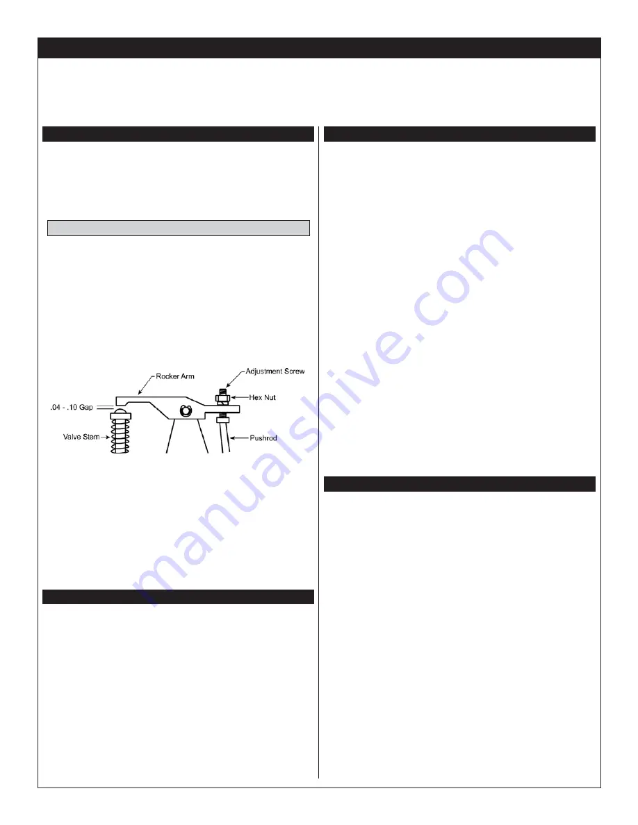
3) The required valve clearance is between .04mm and .10mm,
measured between the valve stem and the rocker arm. Use feeler gauges
(available at auto-parts stores) to check the clearance. The .04mm feeler
gauge should pass through the gap with only slight friction. The .10mm
feeler gauge should be tight.
q
4) Working with one valve at a time, loosen the locking nut, using
a small wrench. Use a screwdriver to turn the adjustment screw
counterclockwise about 1/2 turn. This will open the gap slightly. Slide
the .04mm feeler gauge between the rocker arm and the valve stem.
Carefully turn the adjustment screw clockwise until the rocker arm touches
the feeler gauge. Using a small wrench, tighten the lock nut.
q
5) Remove the feeler gauge and double-check the gap. Repeat step
# 4 if necessary to achieve the correct setting, then repeat the process
for the second valve assembly.
The timing must be reset if the crankshaft and/or camshaft has been
disassembled. In very rare cases the timing may need to be reset to
restore performance.
q
1) Remove the camshaft housing cover on the side of the crankcase
by first unscrewing the two socket-cap screws.
q
2) Rotate the crankshaft until the piston is at top-dead center, verified
by looking through the glow plug hole.
q
3) With the piston at top-dead center, position the camshaft with the
small punch mark facing toward you and pointing down toward the bottom
of the crankcase. Install the camshaft so that the punch mark is one tooth
ahead (toward the front of the engine) of the 6 o'clock position.
q
4) Reinstall the camshaft housing cover.
RESETTING THE TIMING
MAINTENANCE
Engine maintenance should be done on a regular basis to ensure that you
keep the engine running in top form, especially over time. Following these
simple maintenance practices will ensure the long life and dependability
you expect from your engine.
l
Avoid running the engine under dusty conditions. If you are in a dusty
environment, we suggest using an air filter over the carburetor.
l
At the end of every flying day, purge the engine of fuel by disconnecting
the fuel line from the carburetor and allowing the engine to run dry of fuel.
l
Use a high-quality after-run oil in the engine after you have purged
the engine of fuel. Inject the oil into the engine through the carburetor
and through the glow plug hole. Rotate the crankshaft several times to
distribute the oil throughout the engine. This will prevent rust from forming
inside the engine, especially on the ball bearings.
l
Wipe the outside of the engine dry using a soft cloth.
l
Use a fuel filter between the fuel tank and the carburetor.
l
Periodically check to make sure all of the engine bolts are tight, including
the muffler and exhaust pipe cinch nuts.
l
Periodically check your fuel system, including the plumbing inside the
fuel tank, for leaks or cracks. We recommend changing the silicone fuel
tubing inside and outside the fuel tank at the start of every flying season
or about once a year.
l
If you have attached a length of fuel tubing to the crankcase breather
nipple, periodically check the tubing for any blockage.
LONG TERM STORAGE
If you will not be using your engine for a long period of time, such
as during the winter, we suggest you take the following precautions to
preserve the reliability of your engine:
l
Run the engine completely dry of fuel as described above. This is
extremely important.
l
Remove the valve cover and camshaft housing cover and apply a
generous amount of after-run oil on and around the rocker arm assembly
and the camshaft. Reinstall the covers.
l
Remove the engine backplate and apply a generous amount of after-run
oil to the engine crankcase and to the rear ball bearing, then reinstall the
backplate.
l
Apply a generous amount of after-run oil to the joint between the
throttle barrel and the carburetor housing to prevent the throttle barrel
from sticking.
l
Remove the glow plug and apply a generous amount of after-run oil into
the cylinder head. Reinstall the glow plug and turn the crankshaft over
several times to distribute the oil.
l
Place the engine in a sealed baggie and remove as much air from the
baggie as possible. Your engine can now be stored for a long period
without worrying about rust or engine degradation.


