
6 - Operation
DynaFlex and DynaFlex Pro| Three-way Secure Card Reader Authenticators | Installation and Operation Manual
Page 30 of 56 (
D998200382-10
)
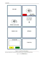
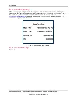
6.3
About the Status LEDs
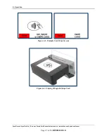
DynaFlex provides four RGB LEDs directly below the chip card insertion slot (see section
), numbered LED1 through LED4, which report the device’s current operating status.
The meaning of each LED depends on the device’s operating mode. See section
and
. Most of the time, operators will check the device’s status
using the LEDs when it is in
Active Mode
while the device is not performing a transaction.
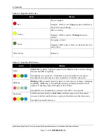
LED colors have specific meanings, as described in
. They are based on international
conventions for traffic light colors, with additional colors reserved for unusual / special cases.
LED blinking patterns have specific meanings as well, as described in
. A blinking LED
generally means the device is actively doing something to change the state that the LED is indicating,
and solid indicates a persistent state that would require an operator or cardholder to take action to
change. One major exception is a device-wide functional failure state, such as a tamper state, where
all LEDs flash urgently to call the attention of an advanced operator to intervene.
In this manual, specific combinations of LED colors and blinking patterns are described in more detail in
the sections where they are relevant, and use the same icons in the tables below to indicate color and
blinking patterns. For example, information about how the LEDs show the device’s connection status is
in section
Table 6-1 - DynaFlex LED Allocation
In This Context
LED1
LED2
LED3
LED4
Active Mode, not armed for
a tap transaction
Power
Connection
Reserved
Card Read Result
Active Mode, armed for a
tap transaction
Armed for Tap Tap Read Progress Tap Read Progress Card Read Result
Device-wide failure
During major failures (such as tamper),
LED1-LED4
report the nature of
the failure based on the most likely steps required to resolve it.


