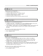
Section 3. Operation
LED INDICATORS
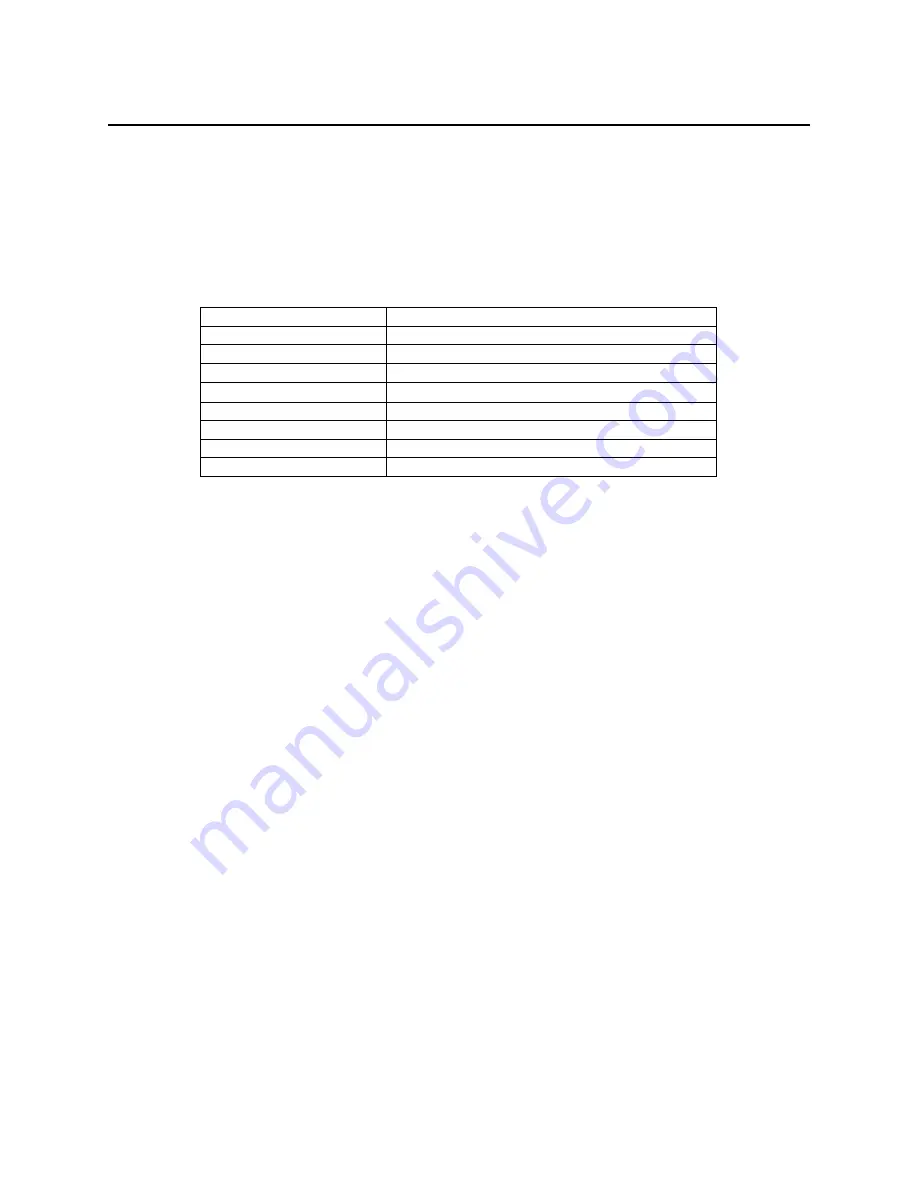
Table 3-1 describes the LED indicator conditions for check and card reading operations. The
LED indicator is located below the slot where the check is first inserted for reading.
Table 3-1. LED indicators
LED INDICATOR
DESCRIPTION
OFF Power
off
SOLID GREEN
Ready to read check or card
OFF
→
SOLID RED
Check read error
OFF
→
SOLID GREEN
Good read
FLASH GREEN
Needs initialization*
FLASH RED/GREEN
Magnetic Interference Detected
FLASH RED/GREEN
Data sensor blocked (motor does not run)*
FLASH RED
Motor sensor blocked (motor does not run)*
*Refer to “Section 4. Troubleshooting Guide.”
CLEANING
Clean the outside of the MICRImage unit with a soft, damp cloth and wipe with a dry cloth.
Caution
To avoid damaging the read head, do not get the inside of the
check or card paths wet.
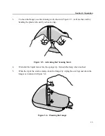
Use the Cleaning Card, P/N 96700004, on the MSR as described below. Use the Cleaning Swab,
P/N 97200078, to clean the Imager Scan Bar as shown and described below.
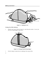
Opening the Unit
To open the check path and Imager, grip the access latch, and pull up and then back as shown in
Figure 3-3.
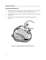
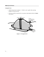
MSR Cleaning Card
Orient the cleaning card similar to Figure 3-2. Swipe the card two or three times to clean the
head.
11
Summary of Contents for MICRImage
Page 8: ...Figure 1 1 MICRImage Check Reader with MSR viii...
Page 12: ...MICRImage Check Reader 4...
Page 30: ...MICRImage Check Reader 22...
Page 32: ...MICRImage Check Reader 24...
Page 34: ...MICRImage Check Reader 26...


