23
APPENDIX A. INTERFACE CABLE PIN LISTS
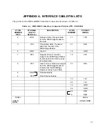
The pin list for the DB9 and DB25 Interface Connectors are shown in Table A-1.
Table A-1. DB9, DB25 Interface Connector Pin List (P/N 22410302)
P1 PIN
NUMBER
DB-9
P1 SIGNAL
(Host as
Reference)
DESCRIPTION P2
PIN
NUMBER
P2 DB-25
SIGNAL
2
RXD
Received Data. Receives data
from the MICRImage Reader to
the Host.
11 TXD
3
TXD
Transmitted Data. Transmits
data from the Host to the
MICRImage Reader.
21 RXD
5 GND
Ground
16 GND
7
RTS
Request to Send. Sends a
signal to the MICRImage Reader
to indicate that the Host is ready
to receive data.
10 CTS
8
CTS
Clear to Send. Receives a signal
from the MICRImage Reader to
indicate that the MICRImage
Reader is ready to send data.
23 RTS
6
DSR
Data Set Ready.
4
DTR
Data Terminal Ready.
13
12V
25
12V
12
GND
24
GND
22
9
DTR
DSR
SHELL
(DRAIN
WIRE)
SHELL
(DRAIN WIRE)
Summary of Contents for MICRImage
Page 8: ...Figure 1 1 MICRImage Check Reader with MSR viii...
Page 12: ...MICRImage Check Reader 4...
Page 30: ...MICRImage Check Reader 22...
Page 32: ...MICRImage Check Reader 24...
Page 34: ...MICRImage Check Reader 26...

