41
Magtrol Model 6530 Three-Phase Power Analyzer
Chapter 4 – Operating Principles
THEOR
Y
4.3.4
RMS
See
Section 4.2.1 – AC Details
4.3.5
C
REST
F
ACTOR
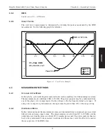
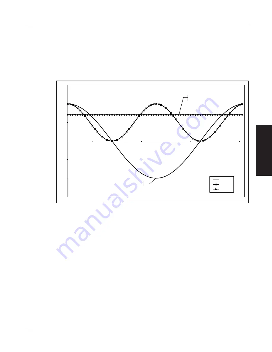
The crest factor measurement is determined by dividing the peak measurement by the RMS
measurement. See the following graph for reference.
-1.5
-1
-0.5
0
0.5
1
1.5
0
50
100
150
200
250
300
350
volts
volts²
V
RMS
Peak 1Volt
RMS 0.707 Volts
CF = Peak / RMS
CF = 1/0.707 = 1.41
Figure 4–3 Crest Factor Example
4.4
MEASUREMENT METHODS
4.4.1
C
YCLE
-
BY
-C
YCLE
M
ODE
In the cycle-by-cycle mode the power analyzer looks at each complete cycle of the incoming waveform.
The measurements are valid from 20 Hz to 500 Hz. The power analyzer may be synchronized from
any of the phase volts or amps inputs, the line voltage or the back panel external sync input. If
using volts or amps for synchronization, the input must be greater than 10% of the range setting.
4.4.2
C
ONTINUOUS
M
ODE
In the continuous mode the measurement values are determined from continuously processed and
filtered volts and amps input values. The measurements are valid from DC to 100 kHz and the
output data rate from the process is about 109.24 samples per second. The power analyzer does not
have to be synchronized to the measured waveform and the user may select the filter to be used in
the mean process of the RMS value.


