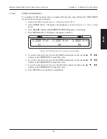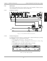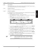
29
Magtrol Model 6530 Three-Phase Power Analyzer
Chapter 3 – Installation/Configuration
SETUP
3.3.6
P
HASE
S
ETUP
Once the wiring mode, measurement filter, external sensor, amp scaling and volt scaling have been
connected and configured, the unit is ready to be configured for each individual phase.
1. To select phase, press PHASE button until desired phase is reached.
2. Select current measurement mode (DC, RMS, peak, crest factor or peak hold).
a.
To select DC press SHIFT and release, then press DC button located in CURRENT
RANGE section of front panel.
b.
To select RMS press SHIFT and release, then press RMS button located in CURRENT
RANGE section of front panel.
c.
To select peak, crest factor or peak hold, press SHIFT and release, then press PEAK-CF
button located in CURRENT RANGE section of front panel. Keep pressing SHIFT
and PEAK-CF buttons until desired selection appears in display. For more information
on peak, crest factor and peak hold, see
Section 4.3 – Measurement Modes
.
3. Select current range by using the
and
buttons located in CURRENT RANGE section
of front panel. Selections include 50 mV, 250 mV, 0.5 V and 1 V when using an external
sensor and 1 A, 5 A, 10 A and 20 A when using amps input.
4. Select voltage measurement mode (DC, RMS, peak, crest factor or peak hold).
a.
To select DC press SHIFT and release, then press DC button located in VOLTAGE
RANGE section of front panel.
b.
To select RMS press SHIFT and release, then press RMS button located in VOLTAGE
RANGE section of front panel.
c.
To select peak, crest factor or peak hold, press SHIFT and release, then press PEAK-CF
button located in VOLTAGE RANGE section of front panel. Keep pressing SHIFT and
PEAK-CF buttons until desired selection appears in display. For more information on
peak, crest factor and peak hold, see
Section 4.3 – Measurement Modes
.
5. Select voltage range by using the
and
buttons located in VOLTAGE RANGE section
of front panel. Selections include 30 V, 150 V, 300 V and 600 V.
6. Press W-VA-PF button until desired selection is reached. Selections include Wx
↑
, Wx,
VAx and PFx where “x” is equivalent to the selected phase.
7. Repeat steps 1-6 for each phase.
8. Once the individual phases have been configured, cycle-by-cycle or continuous must be
chosen. See
Section 4.4 – Measurement Methods
.
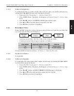
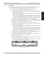
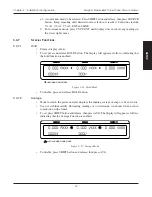
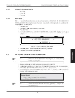
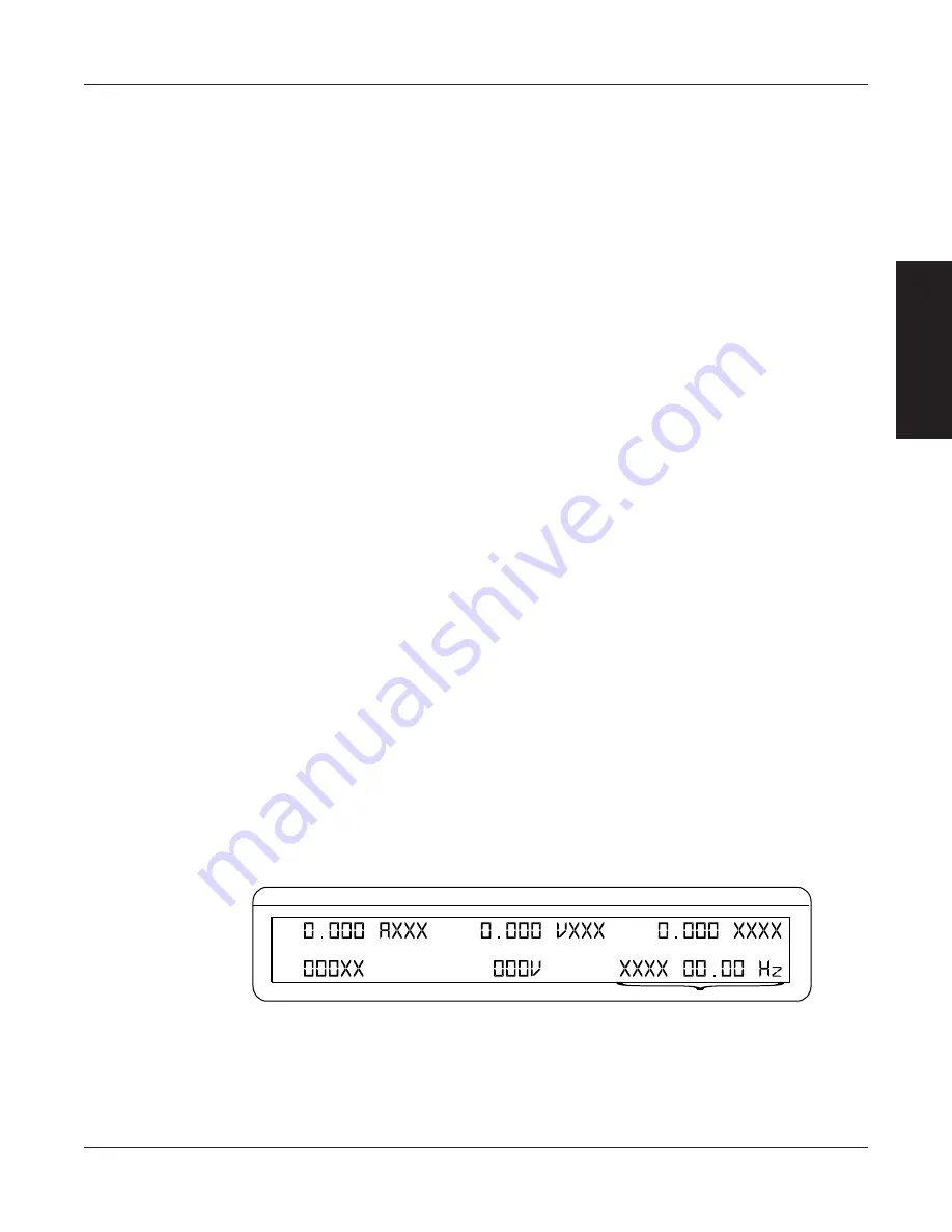
a.1. For cycle-by-cycle mode, press CYC-CONT button until display shows source reading
in lower right corner similar to the following figure.
CURRENT
VOLTAGE
POWER/PF
SOURCE READING
Figure 3–25 Cycle-by-Cycle Mode

