32
THEOR
Y
4. Operating Principles
4.1
ANALOG PROCESSING
4.1.1
V
OLTS
The volts signal is brought in through a precision voltage divider of 2 M and 2.4 k resistors. The
gain is 0.0012. This signal is buffered (GAIN = 1) and passed into a programmable gain section.
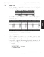
The gains for the voltage ranges are given below.
e
g
n
a
R
s
r
o
t
s
i
s
e
R
)
r
e
i
f
i
l
p
m
A
(
n
i
a
G
t
l
o
v
0
3
0
2
6
/
k
2
1
5
3
.
9
1
-
t
l
o
v
0
5
1
0
2
6
/
k
4
.
2
1
7
8
.
3
-
t
l
o
v
0
0
3
0
2
6
/
k
2
.
1
6
3
9
.
1
-
t
l
o
v
0
0
6
0
2
6
/
0
2
6
0
0
0
.
1
-
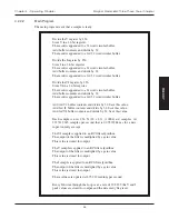
The signal is then presented to an AD7722AS 16-bit analog to digital converter. The part accepts an
input signal of ± 1.25 volts centered on a 2.5 VDC volt bias. The chart below shows system input at
10% and 100% of range.
e
g
n
a
R
)
C
D
V
(
n
I
s
t
l
o
V
)
l
a
t
o
t
(
n
i
a
G
t
u
p
n
I
D
/
A
t
a
s
t
l
o
V
s
t
i
B
t
l
o
v
0
3
3
0
2
2
3
2
0
.
0
-
7
9
6
0
.
0
-
6
2
8
1
t
l
o
v
0
3
0
3
0
2
2
3
2
0
.
0
-
6
6
9
6
.
0
-
1
6
2
8
1
t
l
o
v
0
5
1
5
1
5
4
6
4
0
0
.
0
-
7
9
6
0
.
0
-
6
2
8
1
t
l
o
v
0
5
1
0
5
1
5
4
6
4
0
0
.
0
-
8
6
9
6
.
0
-
5
6
2
8
1
t
l
o
v
0
0
3
0
3
3
2
3
2
0
0
.
0
-
7
9
6
0
.
0
-
7
2
8
1
t
l
o
v
0
0
3
0
0
3
3
2
3
2
0
0
.
0
-
9
6
9
6
.
0
-
9
6
2
8
1
t
l
o
v
0
0
6
0
6
0
0
2
1
0
0
.
0
-
0
2
7
0
.
0
-
7
8
8
1
t
l
o
v
0
0
6
0
0
6
0
0
2
1
0
0
.
0
-
0
0
2
7
.
0
-
4
7
8
8
1
:
n
o
i
t
u
l
o
s
e
R
r
e
t
r
e
v
n
o
C
7
9
6
4
1
8
3
0
0
0
0
.
0
=
6
3
5
5
6
/
5
.
2
=
6
1
^
2
/
5
.
2

