43
Magtrol Model 6530 Three-Phase Power Analyzer
Chapter 5 – Computer Controlled Operation
OPERA
TION
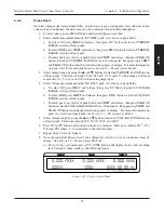
Some PC interfaces can access from one to fifteen 4-bit primary addresses. Other interfaces can
access as many as thirty-one 5-bit primary addresses. The 6530 uses the 4-bit format. For setup,
complete the following instructions utilizing the USER MENU control buttons.
1. Press ENTER.
2. Use the
and
buttons until I/O is reached.
3. Press ENTER.
4. Use the
and
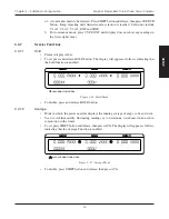
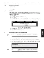
buttons until GPIB ADDRESS is reached. The display should appear as
follows:
CURRENT
VOLTAGE
POWER/PF
Figure 5–2 GPIB Address Setup Menu
5. Use the
and
buttons until desired primary address is reached (range 0-15).
6. Press ENTER to return to main menu.
5.2
ABOUT THE RS-232 INTERFACE
The 6530 is equipped with an RS-232 (serial) interface that communicates with the host computer
through a DB-9 interface connector. The connector pin-out consists of 2-RX, 3-TX and 5-GND.
5. GND
1.
6.
9.
3. TX
8.
2. RX
4.
7.
1
4
3
2
5
6
9
8
7
Figure 5–3 RS-232 Interface
5.2.1
C
ONNECTION
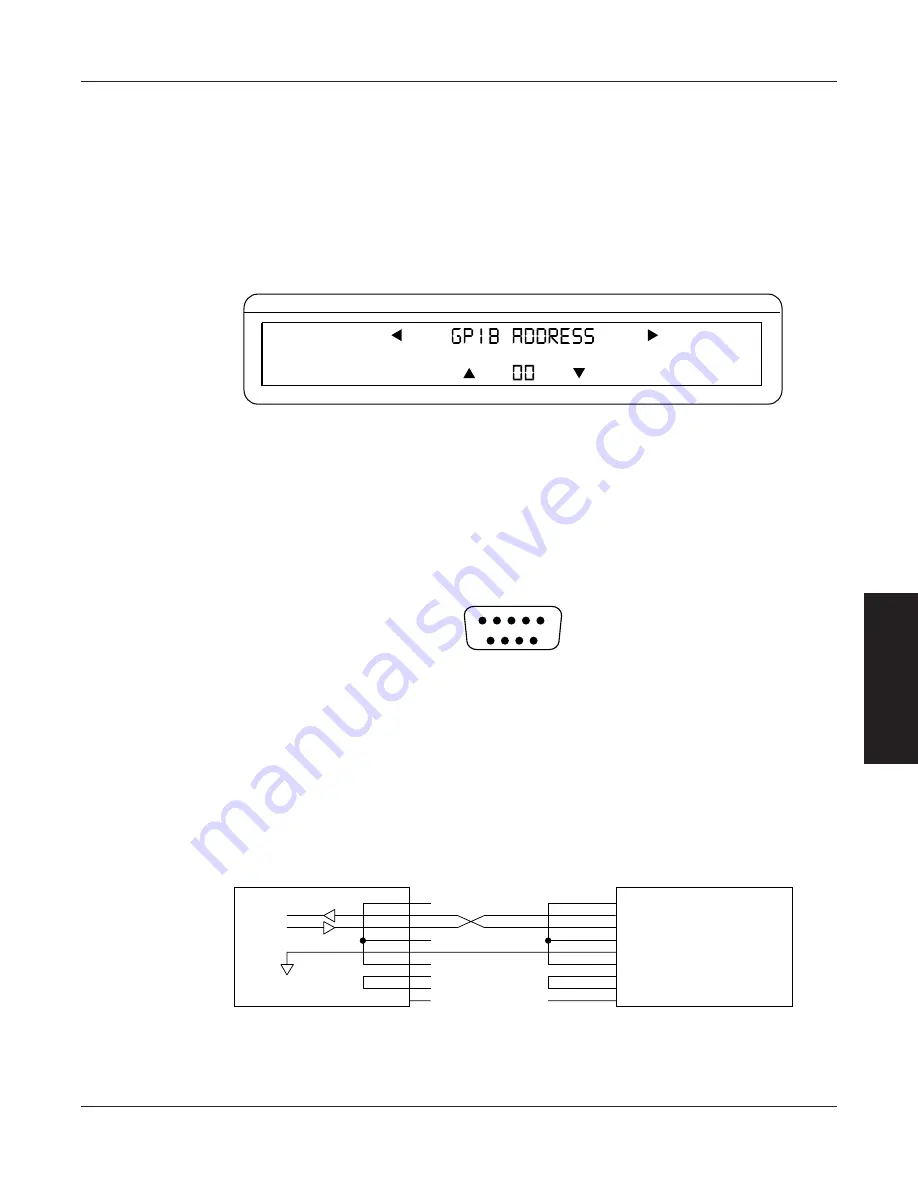
The RS-232 requires null modem wiring. To install use a null modem connector cable, which can
be purchased from your local electronics store.
DIGITAL GROUND
4.
2.
3.
6.
1.
5.
7.
8.
9.
6530
PC
5. GND (SIGNAL GROUND)
1. DCD (DATA CARRIER DETECT)
6. DSR (DATA SET READY)
3. TX (TRANSMIT DATA)
2. RX (RECEIVE DATA)
4. DTR (DATA TERMINAL READY)
9. RI (RING INDICATOR)
8. CTS (CLEAR TO SEND)
7. RTS (REQUEST TO SEND)
RX
TX
GND
Figure 5–4 Cable Connection Using Null Modem

