52
Magtrol Model 6530 Three-Phase Power Analyzer
Chapter 6 – Calibration
MAINTENANCE
6.4
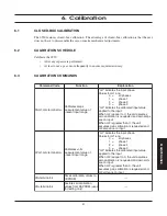
BASIC CALIBRATION PROCESS
A
N
A
L
O
G
O
U
T
P
U
T
A
±
±
V
±
V
±
V
±±
±
±
A
V
A
±
EXT.
SYNC.
EARTH
GROUND
20VA 50/60Hz
FUSE (5x20mm)
CAUTION: DOUBLE POLE FUSING
120V UL/CSA 250mA 250V SB
240V IEC 160mA 250V T
RS-232C
GPIB/IEEE-488
MAGTROL INC.
20 A
AMPS
750 V
VOLTS
MAX.
EXT.
MAX.
1000 V
MAX.
MAX.
±10 V
SENSOR
20 A
AMPS
750 V
VOLTS
MAX.
EXT.
MAX.
1000 V
MAX.
MAX.
±10 V
SENSOR
20 A
AMPS
750 V
VOLTS
MAX.
EXT.
MAX.
1000 V
MAX.
MAX.
±10 V
SENSOR
EARTH
HIGH
CURRENT
LOW
IN
LOCK
PHASE
OUTPUT
PHASE
VARIABLE
LOW
VOLTS, HIGH
VOLTS
EQUIVALENT
FLUKE 5700A OR
VOLTAGE CALIBRATOR
EQUIVALENT
FLUKE 5100A OR
FLUKE 5700A OR
VOLTAGE CALIBRATOR
EQUIVALENT
GUILDLINE 7620A, OR
FLUKE 5725A, 5205A
TRANSCONDUCTANCE AMP.
OPTIONAL-FOR AMPS >2
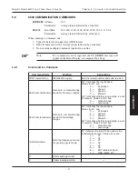
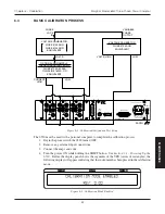
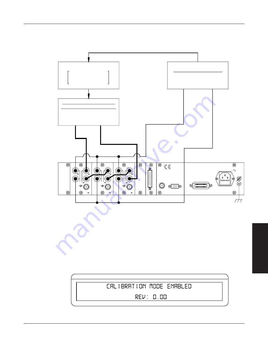
Figure 6–1 Calibration/Verification Test Setup
The 6530 must be used with a personal computer to complete the calibration process.
1. Begin the process with the 6530 turned OFF.
2. Remove any external input connections.
3. Connect the amps and volts.
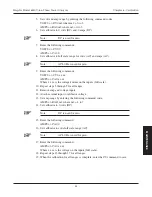
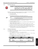
4. Turn the power ON while holding the SHIFT button. See
Section 3.1 – Powering Up the
6530
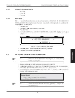
. Before the display panel shows the segments of the VFD (series of rectangles), the
following display will appear indicating that the instrument has been placed in the calibration
mode.
CURRENT
VOLTAGE
POWER/PF
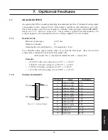
Figure 6–2 Calibration Mode Enabled

