VL-VLP IM 19 JUNE 2017 © 2017 NOVATEC, Inc. All Rights Reserved
Page 18
11.4- VL-12 through VL-38 and VLP-12 through VLP-38 MOTOR BRUSH
REPLACEMENT
1.
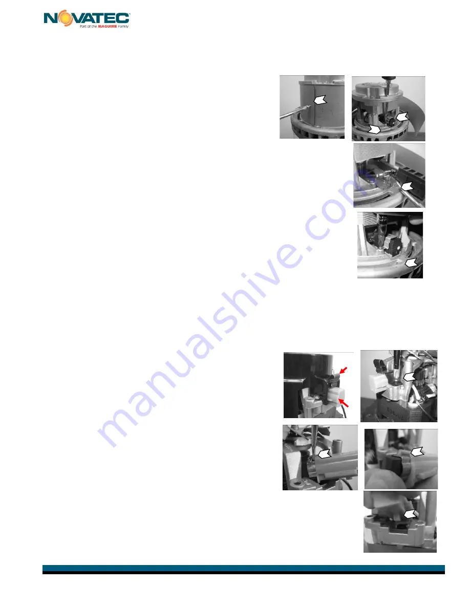
Remove metal band from mid-section of motor
by unscrewing the sheet metal screw in the
side. Pull the cover back away from the motor,
sliding it gently over the wires that pass through
the grommet opposite the screw. The brushes
are visible inside, towards the base of the
motor.
2.
Remove the screws on each side of each brush that hold the
brush retaining clip. A screwdriver may be inserted through the
holes in the top of the motor to aid in this process. Remove the
clip carefully to be sure nothing drops into the motor fan housing
opening towards the middle of the motor.
3.
The brush is contained within a plastic holder and is connected to
the electrical lead through a spade lug terminal. Gently pull or pry
the lug off the brush holder taking care to not damage the lead or
the lug.
4.
New brush may be installed by reversing the above steps. When
securing the brush in the motor housing with the retainer clip, be
sure the brush is properly nested in the motor frame before
securing the screws.
5.
Repeat steps 2 thru 4 for the adjacent brush.
6.
Replace the metal band onto the mid-section, while carefully routing the wires through
the grommet. It is notched to fit in only one position. Secure with single screw.
Reinstall cover over motor.
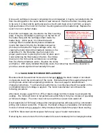
11.5- VL-5, VLP-5 MOTOR BRUSH REPLACEMENT
Remove metal cover from motor.
1.
Remove plastic shield from top of motor by
squeezing the top of each spring clip (A) while
prying the cover up away from colored brush
holder (green-120 volts, red-220 volts). Cover
can be worked up and off, one side at a time.
Take care to not break small positioning stubs
and grip tabs (B) on the plastic cover.
2.
Remove two black screws that hold down brush
retaining clip. Once removed, brush will be
released, but still connected to the short
electrical lead. Use caution to avoid damaging
the lead.
3.
Pry electrical lug out of the brush holder in the direction of the motor
armature, taking care to not separate the wire from the lug.
4.
New brush may now be connected to the electrical lead by reversing
this procedure. Push the lug firmly between the brass brush holder
and its plastic housing.
1
2
3
4
A
B
1
2
3
4
5


