41
BA023001-en
4.3.2
Electrical installation
NOTICE
•
The cable cross-section of the on-site supply cable depends on the local conditions
(e.g. ambient temperature, type of installation, cable length, mains impedance)
and the local regulations.
•
During installation and regular maintenance work, authorised and trained person-
nel must check that all electrical terminals are firmly seated and retighten all elec-
trical screw terminals.
1
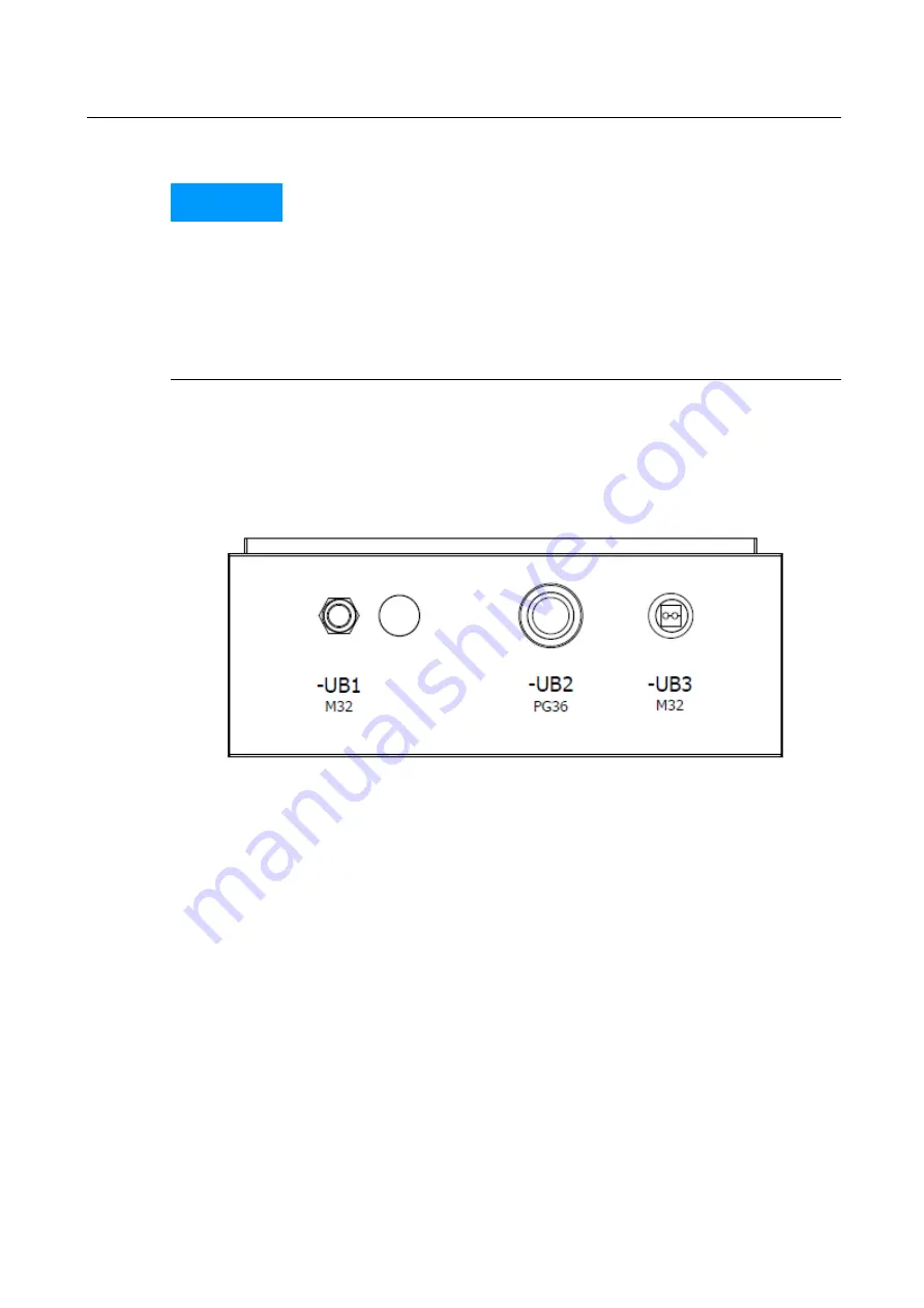
Insert the supply cable via the cable gland -UB1 (M32) on the underside of the
control cabinet and tighten the cable gland using an open-end wrench. Tension
check on the cable, whether the cable gland closes correctly.
2
Fix the supply line to the wall so that there is no tensile load on the screw
connection.
3
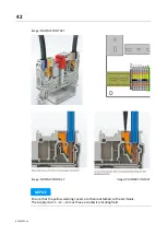
Connect the single wires of the stripped supply cable to the push-in supply cable
terminals -X1L without tensile load. To do this, strip the insulation from the
individual wires 10...12 mm. Make sure that the spring-loaded terminal does not
squeeze on the insulation of the single wire.
The maximum possible wire cross-section of the terminal is 6.0 mm² for solid or
flexible wire (without ferrule).
L1
–
Phase 1
L2
–
Phase 2
L3
–
Phase 3
N
–
Neutral conductor
PE
–
Protective conductor
Summary of Contents for CONNECT Series
Page 19: ...19 BA023001 en 2 3 2 Set up diagram Set up diagram I ...
Page 20: ...20 BA023001 en Set up diagram II ...
Page 22: ...22 BA023001 en 2 4 1 Wiring diagram ...
Page 23: ...23 BA023001 en 2 4 2 Control cabinet structure Basic variant ...
Page 24: ...24 BA023001 en 2 4 3 Control cabinet structure Full equipment ...
Page 25: ...25 BA023001 en ...
Page 53: ...53 BA023001 en ...
Page 138: ...138 BA023001 en 13 Annex 13 1 Naming convention ...


