28
BA082901-en
Pos: 94 / Technische Dokumentation/Alle Geräte/Überschriften/ Überschriften 1.1.1/M/Überschr ift 1.1.1: Manuelles Absenken m it 2 x 5,5 kW- Aggregat im Bed ienp ult @ 35\m od_1390480286490_ 75.d ocx @ 1881094 @ 2 @ 1
5.10.5
Manual Lowering with 2 × 5.5 kW Power Unit in the Control Desk
Pos: 95 / Technische Dokumentation/Hebetechnik/DUO/082901 DUO CM/BA/Inhalt: 0829 M an. Absenken - Aggregat Pult CM 4 ( Tex t) @ 43\m od_1447682773489_ 75.docx @ 2341582 @ @ 1
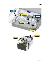
Disengage Latch
If the latch can be disengaged, continue to point “Perform Manual Lowering”.
1 Use hand pump.
Raise the sides one after the other – the seat valve (+C-M5.A / +C-M5.B) on
the other side must remain active in each case.
a) Disable seat valve +C-M5.A or +C-M5.B.
Unscrew and remove the protective cap from the valve and unscrew the
knurled screw (anticlockwise).
b) Disengage latches.
Use the hand pump until latch is fully disengaged.
Warning! Be aware of offset!
c) Enable seat C-M5.A or +C-M5.B/bring them to an operating state.
Re-screw knurled screw (clockwise), attach protective cap.
2 Repeat actions for other side.
Perform Manual Lowering
1 Disable seat A-M1.A and +B-M1.B (main cylinder).
Unscrew and remove the protective cap from the valve and unscrew the
knurled screw (anticlockwise).
2 Place sliding shoe underneath latches on side +A and +B (main cylinder).
3 Leave hazard zone.
4 Lower the lift.
a) Lowering process:
Operate bypass stop C-M4.A and/or +C-M4.B manually – lift lowers!
Warning! Be aware of offset throughout entire lowering process!
5 Remove vehicle.
6 Determine cause of fault and rectify it.
7 Raise the lift without any load.
Warning: Lift may lower a few millimetres when the “UP” button is pressed!
8 Remove sliding shoes (main cylinder).
9 Enable seat A-M1.A and +A-M1.B/bring them to an operating state.
Re-screw knurled screw (clockwise), attach protective cap.
Pos: 96 /----- Format-----/MAN UELLER UM BRUCH Seitenumbruch @ 0\m od_1134403577687_ 0.docx @ 1277 @ @ 1


