background image

13


BA550401-en 


Attach the pit jack with a round sling to the front lift rollers. 


Lift the pit jack from the pallet with the hoist and place it on 

level

 ground. Then 

remove the round sling. 

Caution: Danger of tipping!


Summary of Contents for MGH Series

Page 1: ...um Name dem Text zuzuweisen der hier angezeigt werden soll Fehler Verwenden Sie die Registerkarte Start um Name dem Text zuzuweisen der hier angezeigt werden soll MGH Pit Jack Original Operating Instr...

Page 2: ...he event of the grant of a patent utility model or design The contents of this edition have been checked with great care However errors cannot be fully excluded Subject to technical change without not...

Page 3: ...Design and Operating Principle 10 2 2 Compressed Air Supply 10 2 3 Specifications 10 2 4 Sample Nameplate 11 3 Transport and Storage 11 4 Installation and Initial Operation 11 4 1 Assembly of the Car...

Page 4: ...4 BA550401 en 10 Contents of the Declaration of Conformity 34...

Page 5: ...1 Personal Injury DANGER indicates an immediate hazard which if not avoided will result in death or severe per sonal injury WARNING indicates a potential hazard which if not avoided could result in d...

Page 6: ...modified without the express written consent of the manu facturer In case of non compliance the declaration of conformity becomes void 1 3 Inappropriate Use WARNING Use in any manner other than that i...

Page 7: ...under the load must be carried out by trained personnel The vehicle or vehicle components may only be raised using the designated points Shortly after lifting the vehicle check the lifting points are...

Page 8: ...there are no objects in the area where the pit jack and the load are moving Do not deliberately swing the lifting equipment Because the carriage on the ground is not secured to prevent tipping placing...

Page 9: ...g and lowering itself on its own or distor tion of the supporting components immediately lower the lift or provide support In case of malfunction or repair disconnect the pit jack from the air supply...

Page 10: ...s other adaptors from our range of accessories can be attached In hydraulic pneumatic pit jacks with rapid lift control the oil in the tank is pressurised with compressed air The oil is thus displaced...

Page 11: ...suspended or loaded properly so that they cannot fall taking into account size weight and the cen tre of gravity Store the packages in a covered area protected from direct sunlight at a low humidity a...

Page 12: ...Assembly of the Carriage Version up to 16 5 t Required Aids and Tools suitable hoist indoor crane forklift truck etc 2 round slings 2 lashing straps 1 ratchet with nut 1 torque wrench wooden board As...

Page 13: ...401 en 1 Attach the pit jack with a round sling to the front lift rollers 2 Lift the pit jack from the pallet with the hoist and place it on level ground Then remove the round sling Caution Danger of...

Page 14: ...14 BA550401 en 3 Remove the transport lock and install the compressed air line...

Page 15: ...BA550401 en 4 Remove and store all four M12 screws in the chassis Then attach a side piece with a round sling pull it out with a crane and place it next to the lift Repeat process with second side pan...

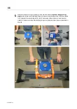
Page 16: ...ers Caution Danger of tip ping and secure with lashing straps At least one second person must be called in to support the assembly work and if necessary other persons must also be called in Make sure...

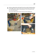
Page 17: ...it laterally with the square spigots into the chassis carriers as far as it will go At least one second per son must be called in to support the assembly work and if necessary other per sons must also...

Page 18: ...t load symmetrically on the lift i e the centre of gravity not the centre should be aligned centrally above the lift Attention Danger of tipping At least one second person must be called in to support...

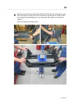
Page 19: ...anel After inserting the second side panel repo sition the chassis centrally on the lift At least one second person must be called in to support the assembly work and if necessary other persons must a...

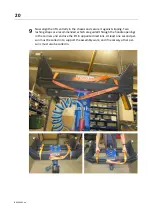
Page 20: ...t slipping Two lashing straps are recommended which are guided through the handle openings in the carriers and enclose the lift in opposite directions At least one second per son must be called in to...

Page 21: ...the hoist diagonally to two jack rollers with a round sling Then lift the jack incl chassis by crane and lower it centrally into the pit The side panels must be pushed in as far as they will go as de...

Page 22: ...jack in the L profile or in the U profile depending on the installation situation If necessary the chassis can be tilted for this purpose if the securing described in step 9 has been carried out corr...

Page 23: ...pull out the side panel until the collars of the chassis rollers are in contact with the pit profile Repeat the process with the second side panel Make sure that both side pa nels are extended to the...

Page 24: ...slings and push the jack through the entire working pit At the widest point of the working pit the clearance between the roller collar and the pit profile may be 5 mm on both sides Then remove the las...

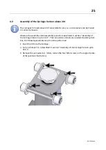
Page 25: ...re described in section Assembly of the Carriage Version up to 16 5 t The same aids and tools are needed Deviating from this the following assembly steps must be performed 1 Insert the lift into the c...

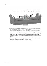
Page 26: ...in contact with the carriage Now observe the procedure for securing the jack described in step 9 in section Assembly of the Carriage Version up to 16 5 t Since the carriages above a load capacity of 2...

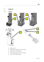
Page 27: ...ration 5 1 Controls A Release spindle B Rapid lift control automatic via remote control C Rapid lift control hand operated D Load lift control automatic via remote control E Load lift control hand ope...

Page 28: ...ring under load When lowering under load the lowering valve may only be opened slowly by turning the release spindle A to the left in order to achieve a controlled descent Lowering without load Open t...

Page 29: ...e of the operating instructions of all equipment and tools used Check lifting accessories carefully for operational safety Pre position the lift and lifting accessory at the lift points Always take up...

Page 30: ...only by authorized and trained service technicians provided by the manufacturer licensed dealers or service partners In case of non compliance the manufacturer s warranty becomes void 6 2 Care Instru...

Page 31: ...ly ensur ing there is a soft transition at the edges Detergent and salt water can freely pene trate and cause considerable damage on the inside Water is dangerous A compressed air service unit consist...

Page 32: ...the hydraulic fluid periodically depending on aging soiling and water ab sorption but after six years at the latest When topping up use fluid with the same specification only If the system was factor...

Page 33: ...y by specially authorized and trained personnel provided by the manufacturer licensed dealers or service partners 9 Disposal If you want to dispose of the equipment please contact your MAHA dealer or...

Page 34: ...d by the EC directives stated below This declaration becomes void if any change is made to the product that was not discussed and approved by named company beforehand Model MGH 5 5 75 MGH 5 5 45 MGH 5...

Reviews: