7
BA042501-en
Pos: 24 /Technische Dokumentation/Alle Geräte/Überschriften/Überschriften 1.1/A/Überschrift 1.1: Aufbau @ 12\mod_1232632872281_75.docx @ 319982 @ 2 @ 1
2.2
Design
Pos: 25 /Technische Dokumentation/Alle Geräte/Überschriften/Überschriften 1.1.1/G/Überschrift 1.1.1: Gewichtssimulator @ 38\mod_1403791709436_75.docx @ 2045316 @ 3 @ 1
2.2.1
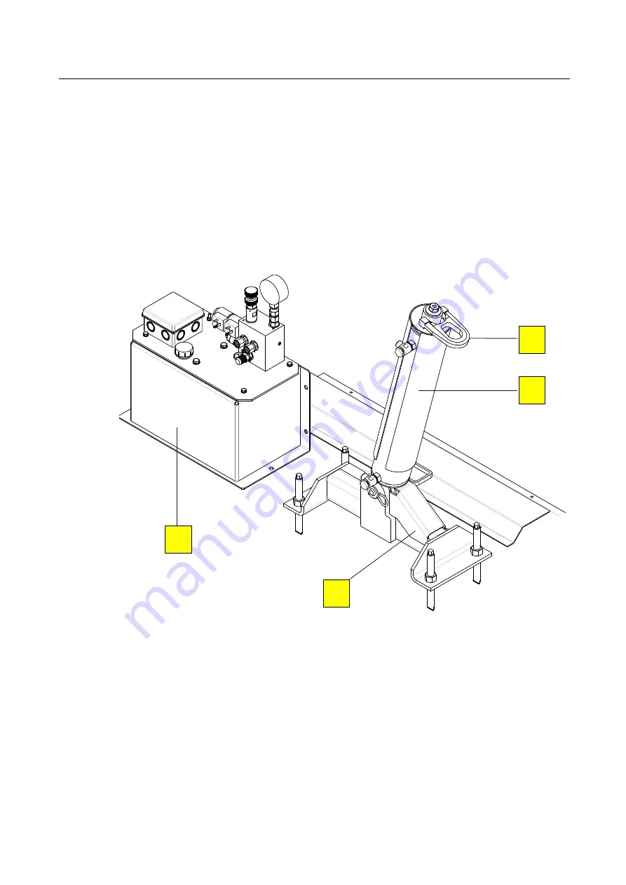
Weight Simulator
Pos: 26 /Technische Dokumentation/Bremsprüftechnik/MBT-SERIES/042501 MLS/BA/Inhalt: 0425 Aufbau MLS (Legende) @ 34\mod_1382614794542_75.docx @ 1845369 @ @ 1
A Hydraulic cylinder
(foldable for MLS 1100 and 2100)
C Lock
B Eyelet for chain slings
D Hydraulic power unit
(Example)
Pos: 27 /Technische Dokumentation/Bremsprüftechnik/MBT-SERIES/042501 MLS/BA/Inhalt: 0425 Aufbau MLS (Bild) @ 34\mod_1382607313523_0.docx @ 1845264 @ @ 1
Pos: 28 /Technische Dokumentation/Alle Geräte/Überschriften/Überschriften 1.1.1/R/Überschrift 1.1.1: Rollensatzanhebung @ 38\mod_1403791920051_75.docx @ 2045362 @ 3 @ 1
2.2.2
Roller Set Lift
Pos: 29 /Technische Dokumentation/Bremsprüftechnik/MBT-SERIES/042501 MLS/BA/Inhalt: 0425 Aufbau RSA @ 34\mod_1382627336243_75.docx @ 1845899 @ @ 1
•
Hydraulic power unit and gear flow divider
The power unit is attached in a foundation recess, and connected to the hydraulic
cylinder via eight tubes.
•
Built-in tub and cylinder
The eight cylinders of the two roller sets are synchronised with each other, i.e. the
roller sets move up and down at the same level, and are secured with stop valves.
Pos: 30 /-----Format-----/MANUELLER UMBRUCH Seitenumbruch @ 0\mod_1134403577687_0.docx @ 1277 @ @ 1
B
A
D
C


