

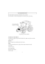


DESCRIPTION
■
General construction
The transmission case, Clutch, Clutch housing, Engine and Front Axle Support are bolted together to
form a rigid unit .
■
Front Axle & Wheels
■
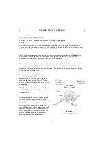
Front Axle & Wheels
The 4WD front axle is a center-pivot, reverse Eliot type. The front wheel drive mechanism is
incorporated as a part of the axle.
The front wheel drive power is taken off the rear transmission and transmitted to the differential in the
front axle where the power is divided into right and left and to the respective final cases.
In the final cases, the transmitted revolution is reduced by the level gears to drive the front wheel. The
4WD mechanism with level gears provides wider steering and greater durability.
■
Engine
■
Engine
The tractors are fitted with fuel efficient
Turbo charged engines
with 4 cylinders of
6110
designed by Daedong.
■
Clutch and Transmission
A single plate dry clutch (10.83"diameter) is used on these tractors. Tractors with IPTO
(Independent Power Take Off) are fitted with hydraulic Clutch Assy. The transmission Gear box has
12 forward & 12 reverse speeds of
6110
. Presently, Mahindra Tractors are fitted with constant mesh
type gears.
type gears.
■
Brakes
Mahindra tractors are provided with independent disc brakes operated by two road travel. A foot
brake lever is fitted for parking.
■
Rear axle & Wheels
This is mounted on ball bearings and is enclosed in removable housings which are bolted to the
transmission case. The rim & Disc fitted with Rear tires are bolted to the outer flange of the Rear
Axle
Axle.
■
Hydraulic system & Linkages.
Mahindra Tractors are fitted with Live (i.e. system is in operation even when clutch is disengaged.)
independent, System. Three point Linkages can be used for Category 2 types of implements.
12
Summary of Contents for 10 Series
Page 1: ...Mahindra USA Inc 5203 Aeropark Drive Houston TX 77032 281 449 7771 www mahindrausa com...
Page 2: ......
Page 3: ......
Page 4: ......
Page 53: ...OPERATING THE 3 POINT LINKAGE TPL 49...
Page 108: ...6110 5010 Gear Cab TYPE WIRING DIAGRAM A3 104...
Page 109: ...6110 5010 Gear Cab ELECTRIC SYSTEM DIAGRAM 105...
Page 110: ...6110 5010 Gear Cab WIRING DIAGRAM 1 106...
Page 111: ...6110 5010 Gear CABIN WIRING DIAGRAM 2 107...
Page 112: ...6110 5010 Gear CABIN WIRING DIAGRAM 3 108...
Page 114: ...6110 Gear POWER TRAIN 110...
Page 116: ...DATE TRACTOR HOURS NATURE TYPE OF REPAIR SERVICE CARRIED OUT SERVICE RECORD 112...
Page 118: ...PART REPLACEMENT RECORD DATE PART DESCRIPTIO N Q TY COST DATE PART DESCRIPTION Q TY COST 114...
Page 119: ......