


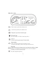


►
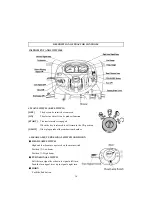
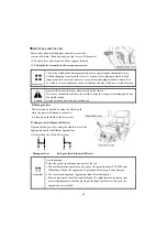
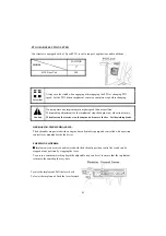
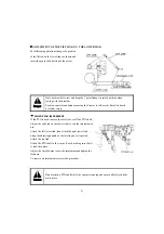
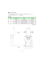
SHUTTLE SHIFT LEVER
This control allows shifting from forward to reverse &
reverse to forward. When stationary set the lever to
N
for neutral
①
Push the lever away from the driver engages forward.
②
Pulling the lever towards the driver engages reverse
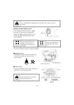
Operate the shuttle shift only while seated on the tractor.
1.Press the clutch pedal down completely before operating the shuttle shift lever.
2.When changing from forward to reverse or back to forward again while in high
range make sure the tractor comes to a stop before changing direction. Failure to do
so is likely to result in damage to the mechanism and place the driver at risk of injury.
Important
②
Pulling the lever towards the driver engages reverse.
p
y
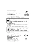
Do not use the shuttle shift lever to start the tractor for towing or traveling uphill, use
the clutch instead.
Always stop the tractor before getting off.
Caution
▶
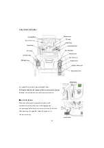
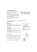
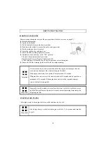
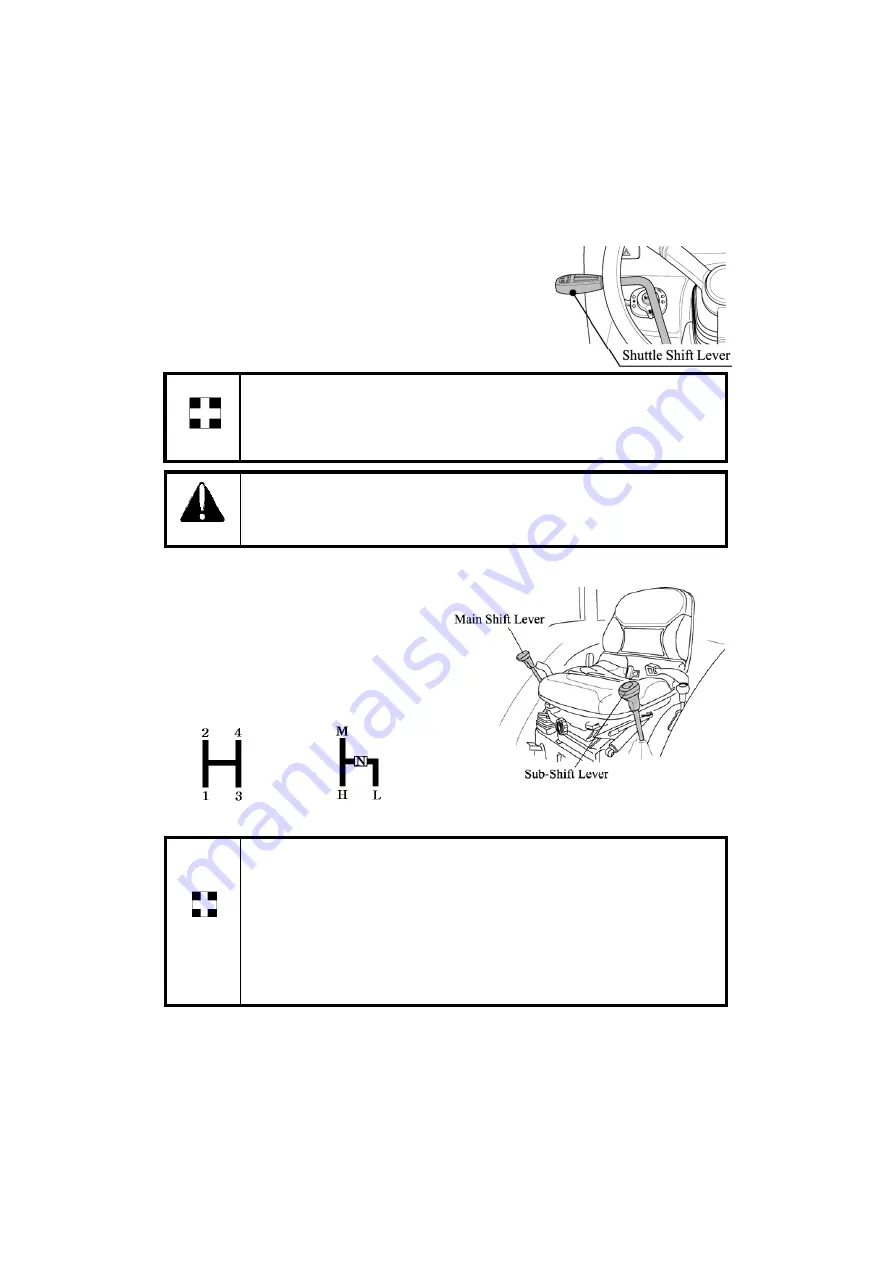
Main gear lever
This lever can be shifted by using the clutch, both
when the tractor is stationary or mobile.
It is located on the RHS of the driver seat.
▶
Sub gear lever(Linear shift lever)
Operate the sub gear lever using the clutch to select the
appropriate speed for different applications.
It is located on the LHS of driver seat.
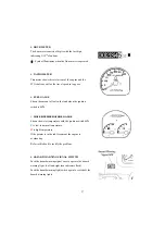
Avoid damage!
Select the proper speed range and gear for the job.
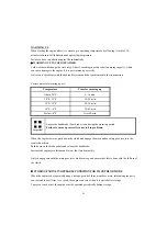
• The machine maybe operated in any gear with engine speeds at 950-2600 rpm.
Within these limits, the engine can be placed under varying load operations.
Main gear lever
Sub gear lever(Linear shift lever)
42
W
ese
s, e e g e c
be p ced u de v y g o d ope
o s.
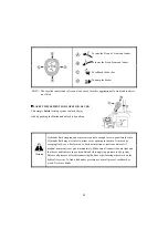
• Never overload engine by lugging machine at low idle speeds.
• Raise engine speed to match expected loads. If a slight increase in engine rpm
occurs simultaneously with the moving of the hand throttle lever forward, the
engine is not overloaded.
Important
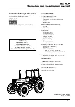
Summary of Contents for 10 Series
Page 1: ...Mahindra USA Inc 5203 Aeropark Drive Houston TX 77032 281 449 7771 www mahindrausa com...
Page 2: ......
Page 3: ......
Page 4: ......
Page 53: ...OPERATING THE 3 POINT LINKAGE TPL 49...
Page 108: ...6110 5010 Gear Cab TYPE WIRING DIAGRAM A3 104...
Page 109: ...6110 5010 Gear Cab ELECTRIC SYSTEM DIAGRAM 105...
Page 110: ...6110 5010 Gear Cab WIRING DIAGRAM 1 106...
Page 111: ...6110 5010 Gear CABIN WIRING DIAGRAM 2 107...
Page 112: ...6110 5010 Gear CABIN WIRING DIAGRAM 3 108...
Page 114: ...6110 Gear POWER TRAIN 110...
Page 116: ...DATE TRACTOR HOURS NATURE TYPE OF REPAIR SERVICE CARRIED OUT SERVICE RECORD 112...
Page 118: ...PART REPLACEMENT RECORD DATE PART DESCRIPTIO N Q TY COST DATE PART DESCRIPTION Q TY COST 114...
Page 119: ......