C-49
35 Series 4WD, Model - 3535, 4035, 4535 and 5035 SM June’08
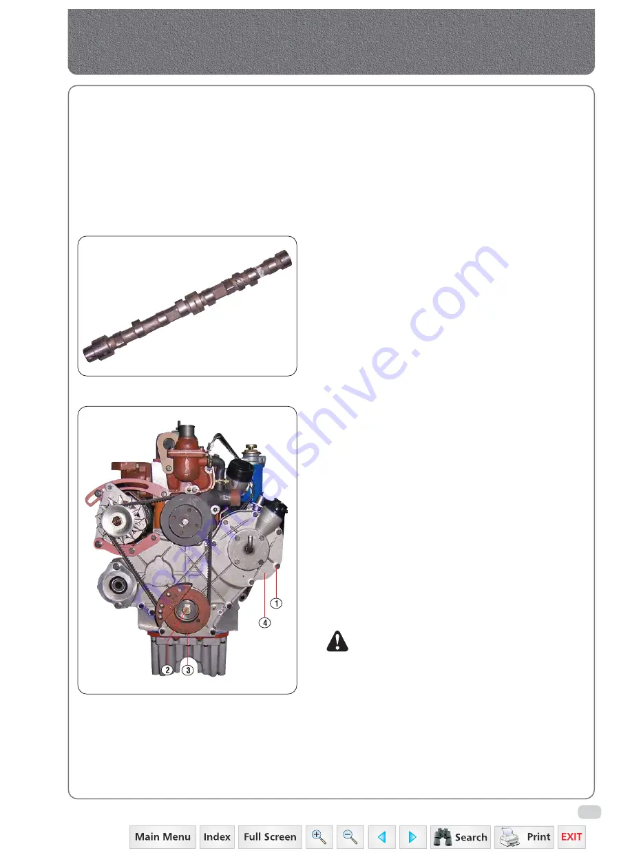
Fig. 1
Timing Gear Train, Front Cover & Camshaft
A.
DESCRIPTION
1.
GEAR TRAIN
The timing gear train consists of four gears.
The Crankshaft pinion, the camshaft gear, the idler
gear and the injection pump gear. These gears
are mounted on the front plate face of the engine
and are covered with the aluminium casting
crankcase front cover. Each gear is punch marked
for timing purpose.
2.
CAMSHAFT
The special cast iron/forged camshaft runs in
babbit lined bushes in the right hand side of the
crankcase. The camshaft bushes are replaceable
and are supplied for service in a semi-finished
bored condition and must be line reamed to size
after filling. A gear integral with the camshaft
provides the drive for the oil pump.
The camshaft is driven from the front end of the
crankshaft through a train of gears. All gears are
punch marked to ensure correct timing. End float
is controlled by thrust washer plate (4-3). The drive
gear is key shrunk to the camshaft end.
B.
FRONT COVER
1.
Removal
a)
Remove the fan belt and fan as detailed in cooling
system.
b)
Remove the bolt (2-1).
c)
Remove front side hydraulic pump mounting bolts
pull hydraulic pump out somewhat and move
slightly towards the outside.
d)
Pull the fan driver pulley (3-1) off the crankshaft
and remove the key.
e)
Remove alternator and alternator bracket.
f)
Remove the bolts from the front cover bottom
and adapter plate.
g)
Remove the bolts (1-1) securing the front cover
(4-1) then remove the cover and gasket.
NOTE:
Check the backlash between the gears to
specifications if necessary.
2.
DISMANTLING
Press out the oil seal if inspection proves it
necessary.
3.
ASSEMBLY
Press in a new oil seal with the lip facing inward
until it is flush with the outside face of the front
cover.
4.
INSTALLATION
Reverse the removal procedure.
Camshaft
Summary of Contents for 3535
Page 1: ...Click here to go on INDEX SERVICE MANUAL 3535 4035 4535 5035 GEAR 35 Series 4WD Main Page ...
Page 5: ......
Page 6: ...35 Series 4WD Model 3535 4035 4535 and 5035 SM June 08 Group A G e n e r a l General A1 A21 ...
Page 7: ......
Page 26: ......
Page 58: ......
Page 59: ...35 Series 4WD Model 3535 4035 4535 and 5035 SM June 08 CHAPTER 1 INTRODUCTION ...
Page 60: ......
Page 74: ......
Page 76: ......
Page 86: ......
Page 88: ......
Page 96: ......
Page 97: ...35 Series 4WD Model 3535 4035 4535 and 5035 SM June 08 CHAPTER 4 LUBRICATION SYSTEMS ...
Page 98: ......
Page 102: ......
Page 104: ......
Page 110: ......
Page 112: ......
Page 124: ......
Page 126: ......
Page 133: ...35 Series 4WD Model 3535 4035 4535 and 5035 SM June 08 CHAPTER 8 COOLING SYSTEM ...
Page 134: ......
Page 143: ...35 Series 4WD Model 3535 4035 4535 and 5035 SM June 08 CHAPTER 9 AIR CLEANER ...
Page 144: ......
Page 149: ...35 Series 4WD Model 3535 4035 4535 and 5035 SM June 08 CHAPTER 10 FUEL SYSTEM ...
Page 150: ......
Page 168: ...35 Series 4WD Model 3535 4035 4535 and 5035 SM June 08 Group D C l u t c h Clutch D1 D10 ...
Page 169: ......
Page 179: ......
Page 180: ...35 Series 4WD Model 3535 4035 4535 and 5035 SM June 08 CHAPTER 1 TRANSMISSION ...
Page 181: ......
Page 200: ...35 Series 4WD Model 3535 4035 4535 and 5035 SM June 08 CHAPTER 2 REAR AXLE ...
Page 201: ......
Page 208: ...35 Series 4WD Model 3535 4035 4535 and 5035 SM June 08 CHAPTER 3 DIFFERENTIAL ...
Page 209: ......
Page 222: ...35 Series 4WD Model 3535 4035 4535 and 5035 SM June 08 CHAPTER 4 DIFFERENTIAL LOCK SYSTEM ...
Page 223: ......
Page 227: ......
Page 228: ...35 Series 4WD Model 3535 4035 4535 and 5035 SM June 08 CHAPTER 5 REAR PTO COVER ...
Page 229: ......
Page 231: ......
Page 232: ...35 Series 4WD Model 3535 4035 4535 and 5035 SM June 08 CHAPTER 6 WET CLUTCH PTO ...
Page 233: ......
Page 236: ...35 Series 4WD Model 3535 4035 4535 and 5035 SM June 08 CHAPTER 7 BRAKES ...
Page 237: ......
Page 243: ......
Page 245: ......
Page 270: ......
Page 296: ...Wiring Diagram 35 Series G 28 35 Series 4WD Model 3535 4035 4535 and 5035 SM June 08 ...
Page 298: ......
Page 303: ...H 7 35 Series 4WD Model 3535 4035 4535 and 5035 SM June 08 STEERING SYSTEM CIRCUIT Steering ...
Page 316: ......
Page 318: ......
Page 358: ......
Page 359: ......
Page 367: ...Range Section Transmission ...


