E-41
35 Series 4WD, Model - 3535, 4035, 4535 and 5035 SM June’08
Differential
b.
BACKLASH AND TOOTH CONTACT BETWEEN
RING GEAR AND SPLINE SHAFT.
1)
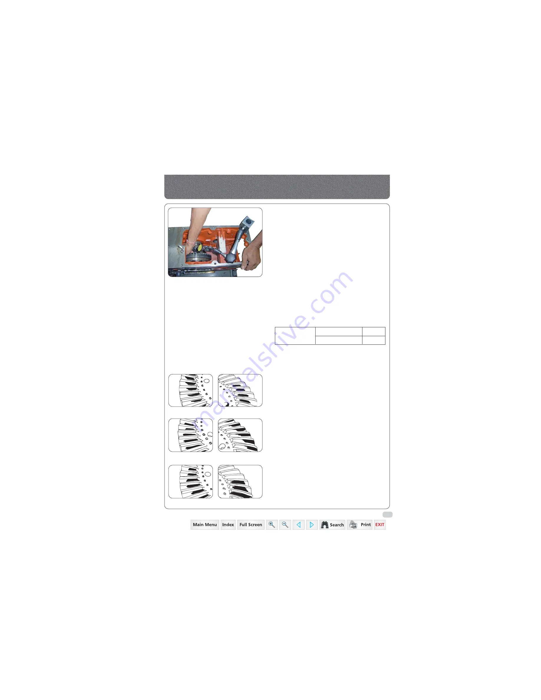
Set the dial indicator between ring gear and Spline
Shaft. Move the ring gear by hand.
2)
When backlash is more, decrease the number of
shims from the ring gear opposite side and insert
the removed shims in ring gear side. When the
backlash is too less decrease the number of shims
from the ring gear side and insert the removed
shims in the opposite side.
3)
Adjust the backlash properly by repeating the
above procedure.
4)
Apply red lead / blue light over several teeth at
three positions equally spaced on the ring gear.
5)
Turn the ring gear, and spline shaft while pressing
a wooden piece against the periphery of the ring
gear.
6)
Check the contact if not proper according to the
instructions below.
More than 35% red lead contact are on the gear tooth
surface.
The center of both contact a 1/3 of the entire width
from the small end.
Adjusting with thicker shims to move spline shaft
backward and place the RH shim to left to move ring
gear left ward.
Repeat above until proper tooth contact and backlash
are achieved.
Fig. A & B gives view of correct markings.
Fig. C & D gives view of setting too far in. This gives
incorrect tooth contact resulting noisy operation and
premature wear of gears.
Fig. E & F shows the markings of a pinion which has
been set too far out. This tends to cause premature
wear of the bevel gear.
If it is necessary to reset the pinion, the backlash will
need to be adjusted.
Fig. A
Fig. B
Fig. C
Fig. D
Fig. E
Fig. F
Backlash between
Ring Gear and
Spline Shaft
Factory specifications
Allowable Limit
0.007 to
0.009 in
0.015 in
Checking Backlash
Summary of Contents for 3535
Page 1: ...Click here to go on INDEX SERVICE MANUAL 3535 4035 4535 5035 GEAR 35 Series 4WD Main Page ...
Page 5: ......
Page 6: ...35 Series 4WD Model 3535 4035 4535 and 5035 SM June 08 Group A G e n e r a l General A1 A21 ...
Page 7: ......
Page 26: ......
Page 58: ......
Page 59: ...35 Series 4WD Model 3535 4035 4535 and 5035 SM June 08 CHAPTER 1 INTRODUCTION ...
Page 60: ......
Page 74: ......
Page 76: ......
Page 86: ......
Page 88: ......
Page 96: ......
Page 97: ...35 Series 4WD Model 3535 4035 4535 and 5035 SM June 08 CHAPTER 4 LUBRICATION SYSTEMS ...
Page 98: ......
Page 102: ......
Page 104: ......
Page 110: ......
Page 112: ......
Page 124: ......
Page 126: ......
Page 133: ...35 Series 4WD Model 3535 4035 4535 and 5035 SM June 08 CHAPTER 8 COOLING SYSTEM ...
Page 134: ......
Page 143: ...35 Series 4WD Model 3535 4035 4535 and 5035 SM June 08 CHAPTER 9 AIR CLEANER ...
Page 144: ......
Page 149: ...35 Series 4WD Model 3535 4035 4535 and 5035 SM June 08 CHAPTER 10 FUEL SYSTEM ...
Page 150: ......
Page 168: ...35 Series 4WD Model 3535 4035 4535 and 5035 SM June 08 Group D C l u t c h Clutch D1 D10 ...
Page 169: ......
Page 179: ......
Page 180: ...35 Series 4WD Model 3535 4035 4535 and 5035 SM June 08 CHAPTER 1 TRANSMISSION ...
Page 181: ......
Page 200: ...35 Series 4WD Model 3535 4035 4535 and 5035 SM June 08 CHAPTER 2 REAR AXLE ...
Page 201: ......
Page 208: ...35 Series 4WD Model 3535 4035 4535 and 5035 SM June 08 CHAPTER 3 DIFFERENTIAL ...
Page 209: ......
Page 222: ...35 Series 4WD Model 3535 4035 4535 and 5035 SM June 08 CHAPTER 4 DIFFERENTIAL LOCK SYSTEM ...
Page 223: ......
Page 227: ......
Page 228: ...35 Series 4WD Model 3535 4035 4535 and 5035 SM June 08 CHAPTER 5 REAR PTO COVER ...
Page 229: ......
Page 231: ......
Page 232: ...35 Series 4WD Model 3535 4035 4535 and 5035 SM June 08 CHAPTER 6 WET CLUTCH PTO ...
Page 233: ......
Page 236: ...35 Series 4WD Model 3535 4035 4535 and 5035 SM June 08 CHAPTER 7 BRAKES ...
Page 237: ......
Page 243: ......
Page 245: ......
Page 270: ......
Page 296: ...Wiring Diagram 35 Series G 28 35 Series 4WD Model 3535 4035 4535 and 5035 SM June 08 ...
Page 298: ......
Page 303: ...H 7 35 Series 4WD Model 3535 4035 4535 and 5035 SM June 08 STEERING SYSTEM CIRCUIT Steering ...
Page 316: ......
Page 318: ......
Page 358: ......
Page 359: ......
Page 367: ...Range Section Transmission ...


