G-14
35 Series 4WD, Model - 3535, 4035, 4535 and 5035 SM June’08
Electrical System
NOTE:
The Starting circuit is interconnected
with the Forward / Reverse system. Thus the
Engine will not start unless the Forward /
Reverse is in neutral.
SWITCHES
Combination Switch
:
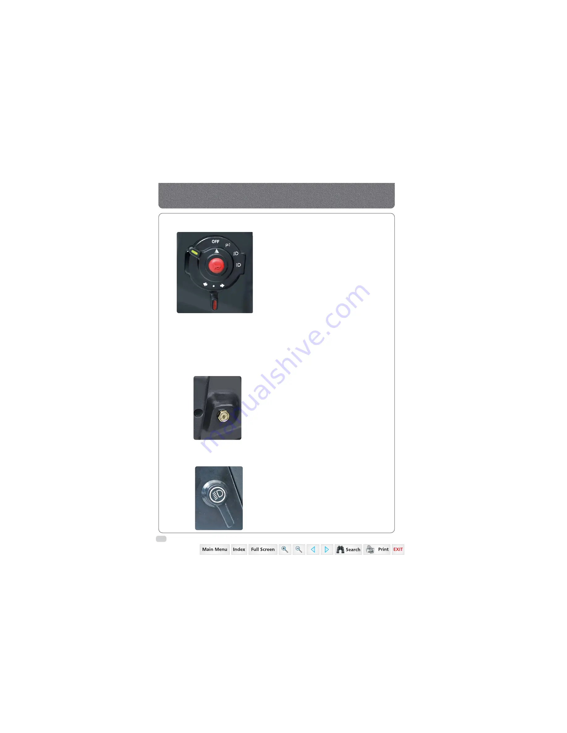
It is located in LH side of steering column on dashboard.
It consists of:
1. Horn (in centre)
2. Light Switch
3. Turn Signal Switch
Horn
Pressing the horn switch will blow the horn.
Light Switch
It is a 4 positions rotary switch. It operates in clockwise
direction and positions are as follows:
1. Off
2. Illuminate Parking Lamp
3. Illuminate low beam of head lamp & Parking Lamp
4. Illuminate high beam of head lamp & Parking Lamp
Turn Signal Switch
This is 3 positions rotary switch. The vertical position of
knob operates in both directions and the positions are
as follows:
1. Vertical - OFF
2. Left - Operates LH Turn signal Lamp
3. Right - Operates RH Turn Signal Lamp
Starter Key Switch
It is a key operated 3 positions rotary switch. It is
located in RH side of steering column on dashboard.
It operates in clockwise direction and positions are as
follows:
1. Off
2. It gives readiness to electrical circuit for operation
of plow lamp switch, combination switch,
instrument cluster.
3. Activates the starting circuit for engine.
Plow Lamp Switch
It is a 2 positions rotary switch located in LH side of
steering column on dashboard. It operates in clockwise
direction and positions are as follows:
1. Off
2. Illuminates the plow lamp
Summary of Contents for 3535
Page 1: ...Click here to go on INDEX SERVICE MANUAL 3535 4035 4535 5035 GEAR 35 Series 4WD Main Page ...
Page 5: ......
Page 6: ...35 Series 4WD Model 3535 4035 4535 and 5035 SM June 08 Group A G e n e r a l General A1 A21 ...
Page 7: ......
Page 26: ......
Page 58: ......
Page 59: ...35 Series 4WD Model 3535 4035 4535 and 5035 SM June 08 CHAPTER 1 INTRODUCTION ...
Page 60: ......
Page 74: ......
Page 76: ......
Page 86: ......
Page 88: ......
Page 96: ......
Page 97: ...35 Series 4WD Model 3535 4035 4535 and 5035 SM June 08 CHAPTER 4 LUBRICATION SYSTEMS ...
Page 98: ......
Page 102: ......
Page 104: ......
Page 110: ......
Page 112: ......
Page 124: ......
Page 126: ......
Page 133: ...35 Series 4WD Model 3535 4035 4535 and 5035 SM June 08 CHAPTER 8 COOLING SYSTEM ...
Page 134: ......
Page 143: ...35 Series 4WD Model 3535 4035 4535 and 5035 SM June 08 CHAPTER 9 AIR CLEANER ...
Page 144: ......
Page 149: ...35 Series 4WD Model 3535 4035 4535 and 5035 SM June 08 CHAPTER 10 FUEL SYSTEM ...
Page 150: ......
Page 168: ...35 Series 4WD Model 3535 4035 4535 and 5035 SM June 08 Group D C l u t c h Clutch D1 D10 ...
Page 169: ......
Page 179: ......
Page 180: ...35 Series 4WD Model 3535 4035 4535 and 5035 SM June 08 CHAPTER 1 TRANSMISSION ...
Page 181: ......
Page 200: ...35 Series 4WD Model 3535 4035 4535 and 5035 SM June 08 CHAPTER 2 REAR AXLE ...
Page 201: ......
Page 208: ...35 Series 4WD Model 3535 4035 4535 and 5035 SM June 08 CHAPTER 3 DIFFERENTIAL ...
Page 209: ......
Page 222: ...35 Series 4WD Model 3535 4035 4535 and 5035 SM June 08 CHAPTER 4 DIFFERENTIAL LOCK SYSTEM ...
Page 223: ......
Page 227: ......
Page 228: ...35 Series 4WD Model 3535 4035 4535 and 5035 SM June 08 CHAPTER 5 REAR PTO COVER ...
Page 229: ......
Page 231: ......
Page 232: ...35 Series 4WD Model 3535 4035 4535 and 5035 SM June 08 CHAPTER 6 WET CLUTCH PTO ...
Page 233: ......
Page 236: ...35 Series 4WD Model 3535 4035 4535 and 5035 SM June 08 CHAPTER 7 BRAKES ...
Page 237: ......
Page 243: ......
Page 245: ......
Page 270: ......
Page 296: ...Wiring Diagram 35 Series G 28 35 Series 4WD Model 3535 4035 4535 and 5035 SM June 08 ...
Page 298: ......
Page 303: ...H 7 35 Series 4WD Model 3535 4035 4535 and 5035 SM June 08 STEERING SYSTEM CIRCUIT Steering ...
Page 316: ......
Page 318: ......
Page 358: ......
Page 359: ......
Page 367: ...Range Section Transmission ...


