B-25
35 Series 4WD, Model - 3535, 4035, 4535 and 5035 SM June’08
Removal & Refitment of Air Cleaner
A. AIR CLEANER
All air entering the engine must pass through the air
cleaner before entering the inlet manifold and cylinders.
To provide an engine with clean and adequate volume
of air, is of utmost importance. The entire system is
so designed that even in extreme dusty conditions and
low Engine R.P.M. the engine is not starved of dust free
air. In this Engine, Dry Type Air Cleaner is placed
horizontally in front of radiator.
The curved blades on the periphery of precleaner shield
direct the entering air to take a spiral path. On entering
the body tube, due to this motion of air, bigger impure
particles are thrown away rapidly from the body tube.
After passing from hopper slot, they fall in the dust
collector. The precleaned air then passes through paper
filter element before entering the engine.
A safety cartridge is provided within the boundaries
of paper element. This can filter particles upto 120
µ
and is of use only in case of any leakage or rupture of
paper element. Also paper element is removed for
cleaning. A mechanical filter clog indicator is provided
which is mounted on air cleaner itself. Whenever red
band of the clog indicator becomes visible, the air
cleaner needs to be cleaned.
NOTE:
Never remove cartridge when paper
element is removed for cleaning.
B. REMOVAL & INSTALLATION INSTRUCTIONS
For Air cleaner Replacement Proceed as follows:
1.
Open the hood.
2.
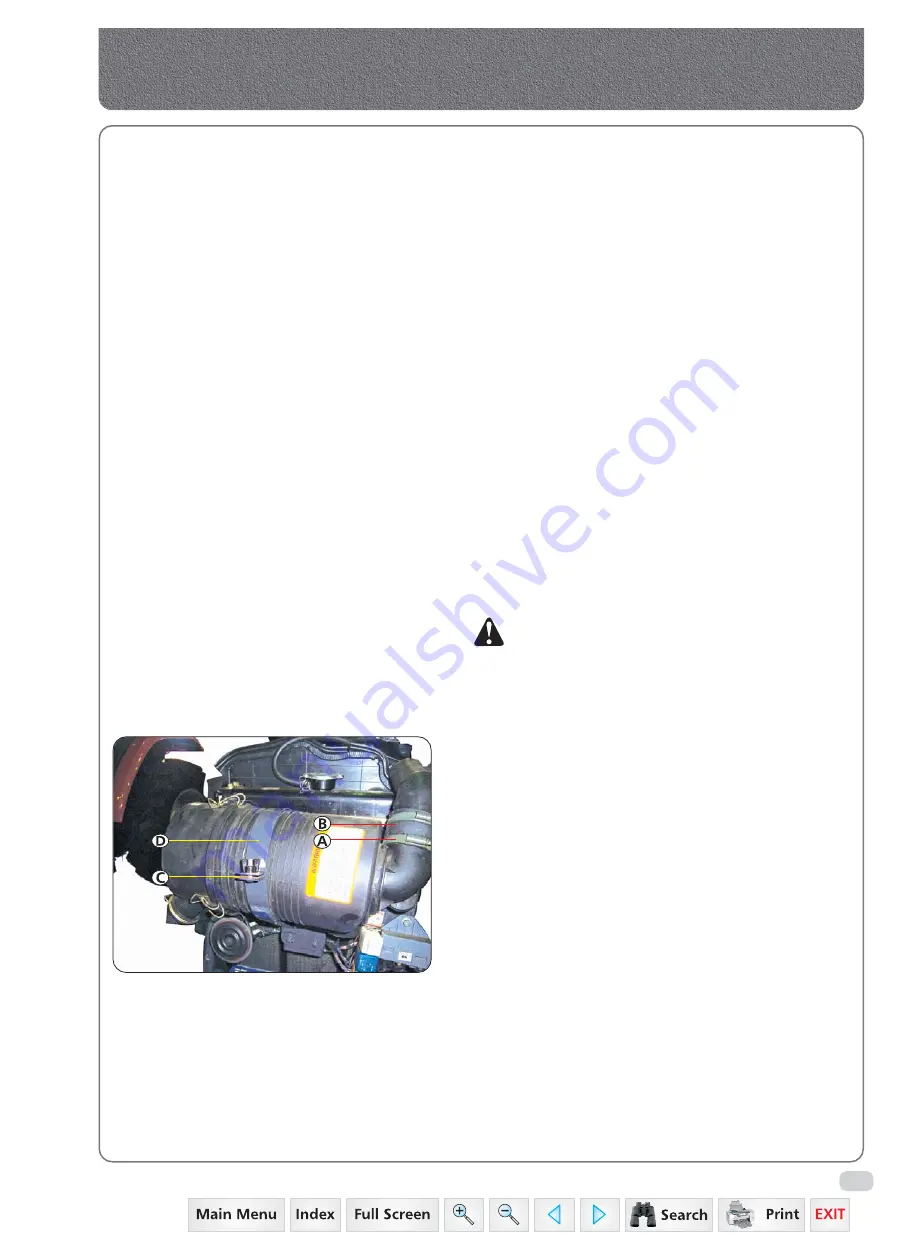
Loosen the hose clips (A) of hose (B) as well as
respective pipes.
3.
Loosen the wing nut (C) & turn the clamp (D).
4.
Remove air cleaner.
Summary of Contents for 3535
Page 1: ...Click here to go on INDEX SERVICE MANUAL 3535 4035 4535 5035 GEAR 35 Series 4WD Main Page ...
Page 5: ......
Page 6: ...35 Series 4WD Model 3535 4035 4535 and 5035 SM June 08 Group A G e n e r a l General A1 A21 ...
Page 7: ......
Page 26: ......
Page 58: ......
Page 59: ...35 Series 4WD Model 3535 4035 4535 and 5035 SM June 08 CHAPTER 1 INTRODUCTION ...
Page 60: ......
Page 74: ......
Page 76: ......
Page 86: ......
Page 88: ......
Page 96: ......
Page 97: ...35 Series 4WD Model 3535 4035 4535 and 5035 SM June 08 CHAPTER 4 LUBRICATION SYSTEMS ...
Page 98: ......
Page 102: ......
Page 104: ......
Page 110: ......
Page 112: ......
Page 124: ......
Page 126: ......
Page 133: ...35 Series 4WD Model 3535 4035 4535 and 5035 SM June 08 CHAPTER 8 COOLING SYSTEM ...
Page 134: ......
Page 143: ...35 Series 4WD Model 3535 4035 4535 and 5035 SM June 08 CHAPTER 9 AIR CLEANER ...
Page 144: ......
Page 149: ...35 Series 4WD Model 3535 4035 4535 and 5035 SM June 08 CHAPTER 10 FUEL SYSTEM ...
Page 150: ......
Page 168: ...35 Series 4WD Model 3535 4035 4535 and 5035 SM June 08 Group D C l u t c h Clutch D1 D10 ...
Page 169: ......
Page 179: ......
Page 180: ...35 Series 4WD Model 3535 4035 4535 and 5035 SM June 08 CHAPTER 1 TRANSMISSION ...
Page 181: ......
Page 200: ...35 Series 4WD Model 3535 4035 4535 and 5035 SM June 08 CHAPTER 2 REAR AXLE ...
Page 201: ......
Page 208: ...35 Series 4WD Model 3535 4035 4535 and 5035 SM June 08 CHAPTER 3 DIFFERENTIAL ...
Page 209: ......
Page 222: ...35 Series 4WD Model 3535 4035 4535 and 5035 SM June 08 CHAPTER 4 DIFFERENTIAL LOCK SYSTEM ...
Page 223: ......
Page 227: ......
Page 228: ...35 Series 4WD Model 3535 4035 4535 and 5035 SM June 08 CHAPTER 5 REAR PTO COVER ...
Page 229: ......
Page 231: ......
Page 232: ...35 Series 4WD Model 3535 4035 4535 and 5035 SM June 08 CHAPTER 6 WET CLUTCH PTO ...
Page 233: ......
Page 236: ...35 Series 4WD Model 3535 4035 4535 and 5035 SM June 08 CHAPTER 7 BRAKES ...
Page 237: ......
Page 243: ......
Page 245: ......
Page 270: ......
Page 296: ...Wiring Diagram 35 Series G 28 35 Series 4WD Model 3535 4035 4535 and 5035 SM June 08 ...
Page 298: ......
Page 303: ...H 7 35 Series 4WD Model 3535 4035 4535 and 5035 SM June 08 STEERING SYSTEM CIRCUIT Steering ...
Page 316: ......
Page 318: ......
Page 358: ......
Page 359: ......
Page 367: ...Range Section Transmission ...


