background image

23


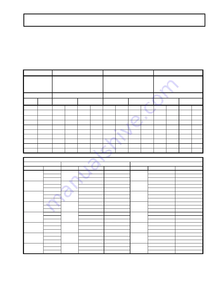
TORQUE SPECIFICATION TABLE 

GENERAL TORQUE SPECIFICATION TABLE 

USE THE FOLLOWING TORQUES WHEN SPECIAL TORQUES ARE NOT GIVEN 


NOTE:

   These  values apply  to  fasteners  as received  from  supplier,  dry  or  when  lubricated  with normal  oil.   They do not 

apply if special graphited or moly disulphide greases or other extreme pressure lubricants are used.  This applies to 

both UNF and UNC threads. 


*

 Thick nuts must be used with grade 8 bolts


SEE G rade No. 


8 * 


BOLT HEAD  

IDENTIFICATION  

MARKS AS PER GRADE 

NOTE MANUFACTURING 

MARKS W ILL VARY 

TORQUE  

TORQUE 

TORQUE 

BOLT SIZE 

 FOOT POUNDS          NEW TON-METERS 

 FOOT POUNDS          NEW TON-METERS 

 FOOT POUNDS          NEW TON-METERS 

Inches 

Millimetre


Min. 

Max. 

Min. 

Max. 

Min. 

Max. 

Min. 

Max. 

Min.   Max. 

Max.


Min. Max. 

Max.


1/4" 

6.35 

6.8 

8.13 

11 

12.2 

14.9 

12 

15 

16.3 

30.3 

5/16" 

7.94 

10 

12 

13.6 

16.3 

17 

20.5 

23.1 

27.8 

24 

29 

32.5 

39.3 

3/8" 

9.53 

20 

23 

27.1 

31.2 

35 

42 

47.5 

57 

45 

54 

61 

73.2 

7/16" 

11.11 

30 

35 

40.7 

47.4 

54 

64 

73.2 

86.8 

70 

84 

94.9 

113.9 

1/2" 

12.7 

45 

52 

61 

70.5 

80 

96 

108.5 

130.2 

110 

132 

149.2 

179 

9/16" 

14.29 

65 

75 

88.1 

101.6 

110 

132 

149.2 

179 

160 

192 

217 

260.4 

5/8" 

15.88 

95 

105 

128.7 

142.3 

150 

180 

203.4 

244.1 

220 

264 

298.3 

358 

3/4" 

19.05 

150 

185 

203.3 

250.7 

270 

324 

366.1 

439.3 

380 

456 

515.3 

618.3 

7/8" 

22.23 

160 

200 

216.8 

271 

400 

480 

542.4 

650.9 

600 

720 

813.6 

976.3 

1" 

25.4 

250 

300 

338.8 

406.5 

580 

696 

786.5 

943.8 

900 

1080 

1220.4  1464.5 

METRIC BOLT TORQUE SPECIFICATIONS 


COARSE THREAD  

Size Screw  Grade No.  Pitch 

(mm)


Foot Pounds 

Newton-Meters  Pitch 

(mm)


Foot Pounds 

Newton-Meters 

M6 

4T 

1.00 


3.6  - 

5.8 


4.9  - 

7.9 


  - 


7T 


5.8  - 

9.4 


7.9  - 

12.7 


  - 


8T 


7.2  -  10 


9.8  - 

13.6 


  - 


M8 

4T 

1.25 


7.2  -  14 


9.8  - 

19    

1.00 


12  - 

17 


16.3  - 

23 


7T 


17  -  22 


23  - 

29.8 


19  - 

27 


25.7  - 

36.6 


8T 


20   -  26 


27.1  - 

35.2 


22  - 

31 


29.8  - 

42 

M10 

4T 

1.50 


20  -  25 


27.1  - 

33.9 

1.25 


20  - 

29 


27.1  - 

39.3 


7T 


34  -  40 


46.1  - 

54.2 


35  - 

47 


47.4  - 

63.7 


8T 


38  -  46 


51.5  - 

62.3 


40  - 

52 


54.2  - 

70.5 

M12 

4T 

1.75 


28  -  34 


37.9  - 

46.1 

1.25 


31  - 

41 


42 

55.6 


7T 


51  -  59 


69.1  - 

79.9 


56  - 

68 


75.9  - 

92.1 


8T 


57   -  66 


77.2  - 

89.4 


62  - 

75 


84 

-  101.6 

M14 

4T 

2.00 


49  -  56 


66.4  - 

75.9 

1.50 


52  - 

64 


70.5  - 

86.7 


7T 


81  -  93 


109.8  -  126 


90  -  106 


122 

-  143.6 


8T 


96  -  109 


130.1  -  147.7 


107  -  124 


145 

-  168 

M16 

4T 

2.00 


67  -  77 


90.8  -  104.3 

1.50 


69  - 

83 


93.5  -  112.5 


7T 


116  -  130 


157.2  -  176.2 


120  -  138 


162.6  -  187 


8T 


129  -  145 


174.8  -  196.5 


140  -  158 


189.7  -  214.1 

M18 

4T 

2.00 

    88  -  100 


119.2  -  136 

1.50 


100  -  117 


136 

-  158.5 


7T 


150  -  168 


203.3  -  227.6 


177  -  199 


239.8  -  269.6 


8T 


175  -  194 


237.1  -  262.9 


202  -  231 


273.7  -  313 

M20 

4T 

2.50 


108  -  130 


146.3  -  176.2 

1.50 


132  -  150 


178.9  -  203.3 


7T 


186  -  205 


252  -  277.8 


206  -  242 


279.1  -  327.9 


8T 


213  -  249 


288.6  -  337.4 


246  -  289 


333.3  -  391.6 

FINE THREAD  

Summary of Contents for BBLST5

Page 1: ...1 READ FOLLOW ALL SAFETY RULES INSTRUCTIONS BEFORE OPERATING YOUR EQUIPMENT 107791 EN R 04062015 ASSEMBLY REPAIR PARTS OPERATION MAINTENANCE 01077910...

Page 2: ...2...

Page 3: ...bly instructions 5 Step 1 Hitch assembly 6 Step 2 3 point hook up 7 ADJUSTMENTS 9 OPERATION 11 TRANSPORT 14 MAINTENANCE STORAGE 15 PARTS BREAKDOWN AND PARTS LIST Rear Blade Standard duty 5 16 Rear Bla...

Page 4: ...EGARDLESS OF THE HAZARD BE EXTREMELY CAREFUL DANGER Signals an extreme hazard that will cause serious injury or death if recommended precautions are not followed WARNING Signals a hazard that may caus...

Page 5: ...2 SAFETY PRECAUTIONS...

Page 6: ...3 SAFETY PRECAUTIONS...

Page 7: ...4 SAFETY LABELS REPLACE IF DECALS ARE DAMAGED FOR DECAL LOCATION SEE PART LIST DECAL 107650...

Page 8: ...D TIGHTEN FIRMLY REFER TO PARTS BREAKDOWN SECTION FOR PART IDENTIFICATION Overall view NOTE In this manual the right and left side is determined being seated on the driver s seat facing forward Remove...

Page 9: ...ly and insert lock pin item 5 Then secure lock pin with cotter pin item 6 Lower parking stand item 7 by pulling the lock pin item 8 in hole B DANGER TO PREVENT INJURIES Rear Blade components are very...

Page 10: ...ES Hooking up equipment to the tractor is dangerous and can result in serious injury or death Do not allow anyone to stand between the tractor and the implement while backing up to the equipment Do no...

Page 11: ...setting Refer to Blade Tilt in the Adjustment section for instructions Raise blade off the ground and angle blade as far as possible towards the right rear tractor tire Refer to Blade Angling in the A...

Page 12: ...body extremities and objects DANGER TO PREVENT INJURIES Always check all hardware for tightness before using or working around the blade Make sure moldboard is secured with nylon insert lock nut CAUT...

Page 13: ...p center 3 point link Increasing blade pitch will increase blade s ability to dig Lengthen center 3 point link to increase blade pitch when grading while traveling forward Shorten center 3 point link...

Page 14: ...e swinging pattern when turning Never hit a solid object with blade as this can damage property and cause tractor to pivot violently resulting in loss of control serious injury or death WARNING TO PRE...

Page 15: ...ions See Check Interferences for detailed instructions Unhooking the Rear Blade Un hook Rear Blade from the tractor as follows Park on a level solid hard surface Place tractor gear selector in park an...

Page 16: ...Grading Instructions when setting the blade depth Backfilling Backfilling is a process where the operator turns the blade around 180 and pushes the product while backing up Be careful not to overstres...

Page 17: ...transporting on a road Install a SMV on the rear blade if tractor s SMV sign is blocked Traffic not alerted to a slow moving tractor might hit the tractor causing serious injury or death WARNING TO P...

Page 18: ...ct service and make necessary repairs to the rear blade when parking it for long periods and when parking it at end of working season This will ensure that the blade is ready for use next time you nee...

Page 19: ...16 PARTS BREAKDOWN PARTS LIST BBLST5 BBLST5 BBLST5 BBLST5...

Page 20: ...17...

Page 21: ...18...

Page 22: ...19 BBLST6 BBLST6 BBLST6 BBLST6...

Page 23: ...20...

Page 24: ...21 BBLST7 BBLST7 BBLST7 BBLST7...

Page 25: ...22...

Page 26: ...298 3 358 3 4 19 05 150 185 203 3 250 7 270 324 366 1 439 3 380 456 515 3 618 3 7 8 22 23 160 200 216 8 271 400 480 542 4 650 9 600 720 813 6 976 3 1 25 4 250 300 338 8 406 5 580 696 786 5 943 8 900...

Page 27: ...__________ _____________________________________________________________________________________________ _____________________________________________________________________________________________ _...

Page 28: ...25...

Reviews: