background image

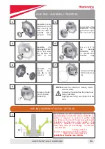
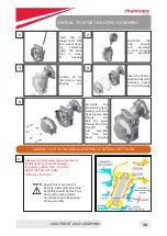
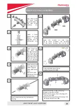
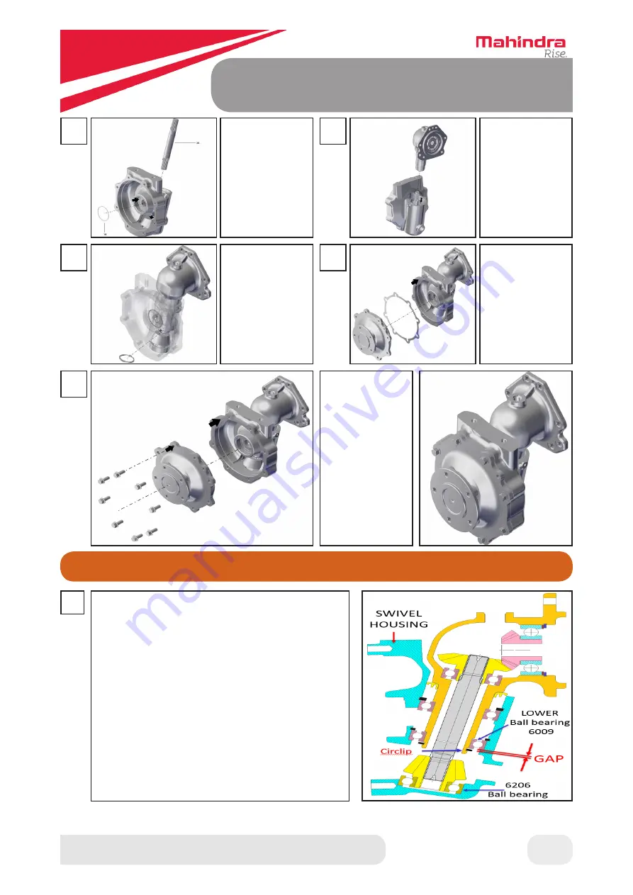
SWIVEL TO SIDE HOUSING ASSEMBLY

4WD FRONT AXLE ASSEMBLY

1

2

Insert the in-

clined  shaft  (33) 

into swivel hous-

ing assembly.

Insert the Shim 

(14)  in  Swiv

-

el Housing

Assemble the 

side housing 

sub assembly 

in Hub Housing 

sub assembly

Fitment of cir-

clip  (34)  on  side 

housing end

Insert the final re

-

duction shims (13) 

between Swivel 

and Hub Housing 

Assemble the 

Swivel Housing as-

sembly with Hub 

Housing assembly

Torque the 

bolt  (4)  Apply 

Torque 41-50 Nm

Transfer of 

sub assembly 

to front axle 

beam housing

3

4

5

34

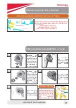
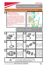
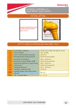
SWIVEL TO SIDE HOUSING ASSEMBLY CRITICAL SETTINGS

Measure the float (up & down movement)

of side housing on swivel housing. 

It should be within 0.10 – 0.20 mm.

Adjust the float with SHIM 

(0.10 mm / 0.50 mm)


Ensure free movement of

                  bearing rollers after assembly.

                  Assembly should be free from

                  dust and foreign particles.

No Grease should be applied

during assembly

NOTE:-

1

Summary of Contents for Jivo 245 DI

Page 1: ...SERVICE MANUAL...

Page 2: ...ront Wheel Toe In 22 13 Front Wiring Harness Layout 23 14 Rear Wiring Harness Layout 24 TRANSMISSION 4WD FRONT AXLE 15 4wd Front Axle Torque Values 26 16 Bearing Oil Seal Position 26 17 Maintenance Sc...

Page 3: ...sembly 56 37 Bullcage Differential Assembly 57 59 38 Brake Assembly Mounting 60 39 Dropbox Assembly Mounting On Rear Housing 61 40 Speed Housing And Clutch Housing Mounting With Rear Housing 61 62 41...

Page 4: ...GENERAL...

Page 5: ...kes Mechanical dry disc type and oil Immersed brakes OIB HYDRAULICS Type Hytech Hydraulics Fully live Hydraulic with Position Draft Controls Lifting Capacity Kgs 450 at Frame and 750 at Hitch TRACTOR...

Page 6: ...PRODUCT SPECIFICATION GENERAL 6...

Page 7: ...hine Practice all other usual and cus tomary safe working precautions and above all REMEMBER SAFETY IS YOUR RESPONSIBILITY YOU ONLY CAN PREVENT SERIOUS INJURY OR DEATH SAFETY DANGER WARNING and CAUTIO...

Page 8: ...MAINTENANCE...

Page 9: ...ash Guard Clean Radiator Fins Clean Coolant Water Check Top Up Fan Belt Fan Belt Tension Check Correct Hydraulics Suction Filter Change Suction Strainer Clean Battery Electrolyte Level Check Battery T...

Page 10: ...0101 Dolly Oil Seal drop box retainer Transmission 5 AGTNYNH0016 Dolly for Rear axle Oil Seal Retainer Transmission 6 AGTNYNH0038 Dolly for Oil Seal Pressing Input Shaft Retainer Transmission 7 AGTNYN...

Page 11: ...l in housing and will avoid repeat seal leakages PROCEDURE TO USE TOOL 1 2 3 4 Place the oil seal on the dolly Hammer seal with the help of dolly Assemble the oil seal on the dolly After pressing the...

Page 12: ...Place the oil seal on the dolly UsetooltotightenlocknutonSpiralBevelShaft withtorquewrench Torquevalue 80 90 Nm PROCEDURE TO USE TOOL PROCEDURE TO USE TOOL Hammer seal with the help of dolly Place oil...

Page 13: ...housing plate AGTNYNH0069 PROCEDURE TO USE TOOL Gauge for checking CCD between bevel pin ion and diff case Place oil seal in Input Shaft Retainer Then using the tool AGTNYNH0038 and ham mer press the...

Page 14: ...URE TO USE TOOL Dolly for pressing slinger and bearing in housing Place slinger on dolly assemble bearing on it Dolly for pressing slinger in side housing Insert dolly with sub assy inside Swivel Hous...

Page 15: ...AGFAYNH0031 Assemble bearing and oil seal on dolly Place oil seal in beam housing and press with tool PROCEDURE TO USE TOOL Dolly for pressing oil seal in beam housing Insert Dolly AGFAYNH0034 with su...

Page 16: ...kages for free movement and adjust free pedal play Belt Slippage Check belt tension and correct it Injector Clogged Check nozzle opening pressure and Corrected it Air cleaner choked Remove check clean...

Page 17: ...asing Points 1 Front Rear Pillow Block 2 2 4WD King Pin Spindle 2 3 Clutch Pedal Brake Pedal 2 2 4 Range Shifter lever 1 5 Bell Crank Assembly 1 6 PTO Lever 1 7 Clutch Shaft Clutch Release Bearing Sle...

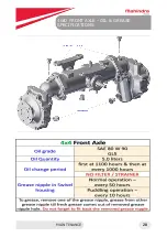
Page 18: ...Every 1000 Hrs 4WD Front Axle Oil Specs Engine Oil Specs Fuel Filter Specs Transmission Oil Specs Oil Grade SAE80W90GL5 Oil Grade API CH4 SAE 15W40 Mahindra M star Genuine Oil Fuel Filter Changed 1st...

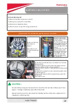
Page 19: ...not open the coolant cap when the engine is hot Do not remove the radiator cap when the engine is hot Checking radiator fins Clean chaff guard daily or earlier if chocked Blow compressed air through t...

Page 20: ...l over flow hose with fingers if a pulsa tion is left when the knob is pumped then no air remain 1 Set the hand throttle lever accelerator at maximum speed position 2 Turn on the key switch to start t...

Page 21: ...be 80 filled with water as follows Remove excess air from Tyre 1 Remove all air from tyre 2 Raise the wheel Rotate the tyre until the valve stem is at 1 O Clock position 3 Remove the valve core housin...

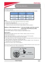
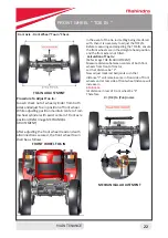
Page 22: ...tance be Y Now adjust track rod ball joints such that distance Y will remain same in front side of front wheels and at rear side of front wheel distance will increase in 4 to 6 mm let distance in rear...

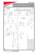
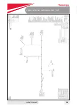
Page 23: ...FRONT WIRING HARNESS LAYOUT MAINTENANCE 23...

Page 24: ...REAR WIRING HARNESS LAYOUT MAINTENANCE 24...

Page 25: ...4WD FRONT AXLE ASSEMBLY...

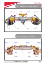
Page 26: ...BEARING OIL SEAL POSITION 4WD FRONT AXLE TORQUE VALUES 4WD FRONT AXLE ASSEMBLY 26...

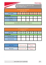
Page 27: ...50 Hours TRANSMISSION Check Oil Level and Top up if necessary Change Oil First at 1100 hours thereafter every 1000 hours Routine Service Schedule Mahindra 4x4 CHECK POINTS 100 Hours 350 Hours 600 Hour...

Page 28: ...4WD FRONT AXLE OIL GREASE SPECIFICATIONS MAINTENANCE 28...

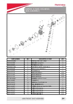
Page 29: ...48X75X17 1 006513300Y1 6 HOUSING Hub 1 006517151Y1 7 SHMS 66X70X0 5 A R 006517154Y1 7 SHIM 46X50X0 1 A R 006517153Y1 7 SHIM 66X70X0 1 A R 001081964R91 8 BEARING 35X72X17 Asian 1 006513360Y1 9 COLLAR...

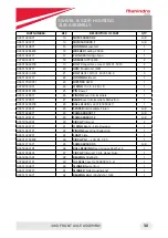
Page 30: ...ediate 1 006513290Y1 27 GEAR Bevel Intermediate Reduction 1 000016299P04 28 BALL BEARING 6307 35X80X21 1 006513385Y1 29 SPACER Intermediate Pinion A R 006514284Y1 29 A R 006513961Y1 29 A R 006505629D1...

Page 31: ...oil seal maximum internal float recommended is 0 30 mm Hence SHIM 7 se lection is required to control it within 0 20 mm if more the lip of the oil seal will invert Calculation must be done when Spindl...

Page 32: ...Ensure free rota tion of circlip af ter fitment in slot Fix the Circlip In ternal 75D 37 to Swivel Housing 2 5 6 3 Press the Cas sette oil seal 56X80X13 5 39 in Swivel Housing with the help of suitabl...

Page 33: ...t e 006513289Y1 Assemble it to Side Housing Fit the O ring 006513337Y1 to Side Housing Outer Groove A s s e m b l e the Spacer 006513385Y1 to Side Housing 2 5 3 33 SWIVEL HOUSING SUB ASSEMBLY CRITICAL...

Page 34: ...Housing Assemble the SwivelHousingas sembly with Hub Housing assembly Torque the bolt 4 Apply Torque 41 50 Nm Transfer of sub assembly to front axle beam housing 3 4 5 34 SWIVEL TO SIDE HOUSING ASSEMB...

Page 35: ...0 200 mm Hence SHIM 14 will be required GAP Measured Gap Recommended Gap 2 Assemble Hub housing on Swivel housing with some End Reduction Shims do not use the shim 14 at present Measure the backlash...

Page 36: ...ETTINGS 1 Measure the gap between circlip bearing Gap should be 0 10 mm maximum Add SHIM differential assembly axial float to adjust the extra gap 2 Measure the backlash between Crown Wheel Pinion wit...

Page 37: ...R 006513391Y1 7 SPACER End 1 006513342Y1 8 BEARING Taper Roller SKF 2 006514372Y1 9 SPACER 31 75X38X0 1 A R 006514290Y1 10 SPACER 31 75X38X6 0 A R 006514289Y1 10 SPACER 31 75X38X5 5 A R 006513990Y1 1...

Page 38: ...r few shims Outer TRB along with outer race Oil seal runner Crimping nut Use suitable pressing dolly 4 Fix the Spline shaft on FIXTURE Torque the Crimping nut 70 N m with a special wrench 5 Wind the r...

Page 39: ...using 2 Apply Torque 95 110 NM 3 Mount Drain plug in beam housing with Torque 50 55 NM 4 Mount Drain plug of Swivel Housing LH RH Apply Torque 50 55 NM Insert bevel pin ion shaft 16 through both pin i...

Page 40: ...t Front pillow Block after mounting the 1 no of O Ring Mount Grease nipple of Front Rear pillow Apply Torque 21 25 NM 10 40 Mount Rear pillow Block after mounting the 2 no of O Ring Mount Knuckle arm...

Page 41: ...ft assembly axial play 0 10 mm 4 Differential Assembly axial float 0 10 mm maximum 5 Crown Pinion backlash 0 10 0 20 mm 6 Bevel Pinion Intermediate FLOAT 0 20 mm maximum 7 Swivel housing float on side...

Page 42: ...TRANSMISSION...

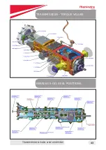
Page 43: ...BEARING OIL SEAL POSITIONS TRANSMISSION TORQUE VALUES TRANSMISSION MAIN LINE ASSEMBLY 43...

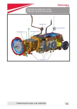
Page 44: ...TRANSMISSION OIL AND GREASE SPECIFICATIONS TRANSMISSION MAIN LINE ASSEMBLY 44...

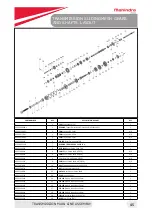
Page 45: ...Bevel Pinion Shaft 0 2 CCD A R 006513089Y1 9 SHIM Bevel Pinion Shaft 0 1 CCD A R 006513091Y1 9 Shim Bevel Pinion Shaft 0 1 CCD A R 006514316Y1 9 SHIM Bevel Pinion Shaft 0 075 CCD A R 007206788C1 10 B...

Page 46: ...uster Low 19T Reverse 19T 1 SF0604038 42 RING Snap 52X1 4 2 006514094Y1 43 GEAR Driven CM 37T 1 006508991U1 44 V RING Speed Driving 1 006513016Y1 45 SPACER Front Gear Cluster Cm Low And Reverse 1 0065...

Page 47: ...using Fitment of ball bearing 6304N on bottom shaft using pressing dolly Fitment of 3rd and 4th driven gear on bottom shaft Fitment of 2nd driven gear on bottom shaft sub assy in speed housing Fitment...

Page 48: ...d 1st and 2nd fork on its gears Fitment of 2nd driven gear on bot tom shaft sub assy in speed housing 5 6 2 3 Assemble detent ball spring detent bolt with washer Apply Torque 65 75 NOTE Use thread loc...

Page 49: ...nd lock both with roll pin R Insert the spring bias S on shaft and Fit cam link inner L with roll pin R Take speed shifter hous ing H and S in hous ing Hpress oil seal O in it Insert the shaft gate sh...

Page 50: ...ter Housing 1 000020313E05 19 BOLT HEXFL M10X1 5X25 5X8 8 4 006513148Y1 20 HOUSING Speed Shifter 1 000020281E05 21 PIN Dowel 2 PART NUMBER REF DESCRIPTION OF PART QTY 006512276V1 22 SPACER Stopper Spr...

Page 51: ...the driving shaft Lip Side of the oil seal should be up side Press in Retainer applying sealant 515 on speed housing with bolt and wash er Apply Torque 20 27 NM on bolts NOTE DO NOT REPLACE Inverted e...

Page 52: ...sure orientation of spacer as shown only Insert NRB in range cluster gear fit this cluster gear assy on driving shaft NOTE Ensure free rotation of NRB With cluster gear assembly Press bearing 6305 on...

Page 53: ...grease nipple in the clutch housing at top side with torque 15 18 N Press 2 Fit Inspection hole cover plate on the clutch Housing using sealant 515 with 4 bolts Apply Torque 20 27 Nm 2 6 7 3 4 Apply G...

Page 54: ...006514305Y1 4 SHIM Rear Axle A R 006517036Y1 4 SHIM Rear Axle 0 05 A R 000017047R1 5 PIN Spring Dowel 4 064 X 0 8128 X 22 352 2 006513402Y1 6 GEAR Bull RH 1 PART NUMBER REF DESCRIPTION OF PART QTY 006...

Page 55: ...8 125 Nm With torque wrench Insert bull gear 6 LH RH in rear housing and mount it on re spective rear axle 6 9 10 7 Fix RAC retain er with 4 bolts 13 to RAC Apply Torque 15 20 NM to bolt REAR AXLE CAR...

Page 56: ...2nd lock nut applying torque 80 90 Nm Again check preload of spline shaft on retainer OD BEVEL PINION SHAFT SUB ASSEMBLY CRITICAL SETTINGS Spiral Pinion shaft bearing preload Using spring balance tyi...

Page 57: ...Trans Spline Shaft FRT 2 006508939U1 8 BOLT M10x1 25x25 Length Oilseal 8 006512433Y1 10 GEAR Side Bevel LH 1 006513546V91 11 PIN Compound Roll For PTO 1 PART NUMBER REF DESCRIPTION OF PART QTY 006512...

Page 58: ...erential Case Mount the bolt 8 apply torque 118 125 Nm Put the diff lock coupling C in the LH diff case through 7 dowel pins D 2 7 8 3 4 5 Fitment of solid pin S roll pin R in the diff lock shaft Inse...

Page 59: ...tial cage Spiral Pinion shaft face GO should go easily NO GO should not go Available thickness of shims for bevel pinion shaft CCD are 0 075 0 1 0 2mm If GO is not going Add some more CCD shims check...

Page 60: ...Grease or oil trace should be present in DRY BRAKE assembly Assembly should be free from dust and foreign particles Make sure liners to be presoaked before assembly of OIB BRAKES Remove all protectiv...

Page 61: ...drop box with applying torque of 60 70Nm Fit dropbox sub assembly below rear housing us ing 4 no of bolts Pressoilseal O indropboxontheshiftingarm Lock the shaft with differential lock washer W and lo...

Page 62: ...RD 16 BOLT M8 X 1 25 X 22 H3 x 2 17 000934309R1 17 WASHERS Spring Lock 17 006514147Y1 18 RETAINER Counter Shaft 1 PART NUMBER REF DESCRIPTION OF PART QTY 006512411Y1 19 RETAINER Lay Shaft With First G...

Page 63: ...Fix it with hose clip h on le ver on dropbox with hose clip H Take speed shifter housing H and press oil seal O in it Insert the shaft gate shifter with spacer stopper S in housing H Insert the gear s...

Page 64: ...housing to Rear housing with bolts B sealant 515 Apply Torque Insert bevel pin ion shaft 16 through both pin ion Press roll pin 11 after aligning DiffCaseandshaft holes by Dolly for roll pin pressing...

Page 65: ...6656Y1 10 LINK Connecting M10 1 000012935P04 11 LOCK Pin Yoke 2 007600776D1 12 YOKE Std M10X1 25 LH 1 000020307E05 13 BOLT M8x1 25x20 1 006509245B1 14 WASHER Aux Lever 1 006513992Y11 15 LEVER Single S...

Page 66: ...797V1 13 WASHER Diff Lock 1 006511675V1 14 LIP SEAL Rotary Shaft 1 006513136Y1 15 CROSS SHAFT Range Shifter 1 006513135Y1 16 CAM Range Shifter 1 006513814V1 17 PIN Compound Roll 8X30 AND 5X30 2 006512...

Page 67: ...l pin R Insert the thrust washer on re verse idler shaft NOTE Washer notch to be oppo site to gear B as shown in figure Mount Gear B on reverse idler shaft with NRB A spacer C NRB D in serted in gear...

Page 68: ...should face upward Lock plate should be hammered on lock nut after Torque NOTE Apply liquid sealant 515 on speed hous ing top cover s C1 mounting area range top cover s C2 mounting area Fix speed top...

Page 69: ...ENGINE...

Page 70: ...DETAILED ENGINE SPECIFICATIONS ENGINE ASSEMBLY 70...

Page 71: ...9 ADAPTER water pump 15 20 STUD mounting FIP to crank Case 16 19 NUT mounting FIP to crank Case 25 30 BOLT mounting Pull to stop lever to pull to stop shaft 08 10 NUT nylock locking pull to stop lever...

Page 72: ...p lever to pull to stop shaft 17 NYLOCKNUT M8 1 25 000020742E05 24 30 For locking pull to stop lever 18 SCREW SOCKET M5X0 8X12X12 9 007205393B1 08 10 For preventing pull to stop shaft to move horizont...

Page 73: ...ng Intake manifold 48 Thermostat Hsg Fitment BOLT Flanged M8 X 1 25 6g X 20 HEX H3 000020307E05 24 30 49 BOLT M8 X 1 25 X 22 000022271RD 24 30 50 BOLT HEX M8X1 25X22X8 8 005557810R1 24 30 51 ADAPTER W...

Page 74: ...r pipe outlet connection 69 FLANGED BOLT M10X25 000020313E05 30 35 For mounting fuel filter to bracket 70 BOLT HEX M8x1 25x14 000020308E05 24 30 For mounting Fuel filter bracket 71 Feed pump Assy BOLT...

Page 75: ...pipes from FIP 4 Remove mounting nuts of FIP to crankcase 5 Push Pull to stop lever towards front so as that it is in between the front and rear pull to stop screws FIP MAY GET DAMAGED IF NOT FOLLOWED...

Page 76: ...lain 0 15 1 1 Plain 0 2 Plain 0 25 1 1 Plain 0 3 1 NBR Coated 0 25 2 3 3 4 4 Slot on control rack rod 1 Make sure to match line on flywheel to hole on flywheel housing 2 Make sure FIP mounting studs a...

Page 77: ...ly stud with 40 Nm torque 4 Do tappet setting 5 Insert gasket Valve housing cover Tighten 2 nos rubber washer cap nut on valve housing cover with 15 Nm torque NOTE TAPPET SETTINGS Filler gauge movemen...

Page 78: ...IN TO THE SYSTEM Procedure for refilling of Coolant in to the system NOTE Replace the coolant after every 1 year 1000 hours Which ever earlier Allow the engine to cool if it is hot 1 Open the hood 2 R...

Page 79: ...not start Engine starts but does not develop full power 1 Low or no fuel pressure a Insufficient fuel Check fuel tank b Fuel oil filter clogged Replace filters c Fuel filter gaskets defective air bei...

Page 80: ...place 16 Foreign object in exhaust manifold from engine Remove clean if damaged replace 17 Restricted exhaust system Remove the restriction 18 Exhaust manifold cracked gasket blown or missing Replace...

Page 81: ...replace 19 FIP defective Repaired by authorised dealer or replace 20 Low engine water temperature Warm engine to normal operating 21 Defective Thermostat Remove Check thermostat D Engine Turns But Wi...

Page 82: ...n nozzles Check for defective injection pump 8 Radiator cap not sealing or defective Replace 9 Defective thermostat Remove and test thermostat Replace if necessary 10 Water pump defective Repair pump...

Page 83: ...se too high Maintain proper oil level 3 Crankcase oil pan gasket leaking Install new gasket 4 Worn valve guides stem seals Install new valve guides stem seals 5 Cylinder sleeves worn distorted Install...

Page 84: ...the high pressure pipe Injector pipes 8 Accelerator cable sticky Replace the cable 9 Air in the fuel system Replace all the banjo washers and check for cracks in fuel line 10 Idling stop out of adjus...

Page 85: ...ween valve stem and guide Ream valve guides for proper clearance M Piston and Cylinder Sleeve Wear 1 Oil of unsuitable grade of viscosity Use oil meeting operator s manual specifications 2 Piston ring...

Page 86: ...d exhaust system Remove restriction or replace parts 7 Defective Fuel Inj Pump Rectify or replace fuel inj pump 8 Worn out rings liners and valves Overhaul Engine R Black Smoke 1 Low Oil level Check e...

Page 87: ...rocker arms 6 Worn valve guides Replace valve guides 7 Valve clearance not OK Adjust clearance 8 Weak valve spring Replace valve spring 9 Wornout gears Replace 10 Broken teeth of gears Replace 11 For...

Reviews: