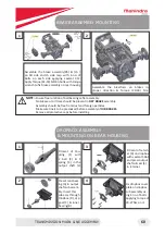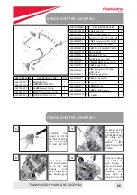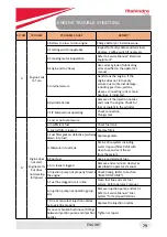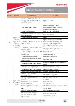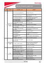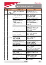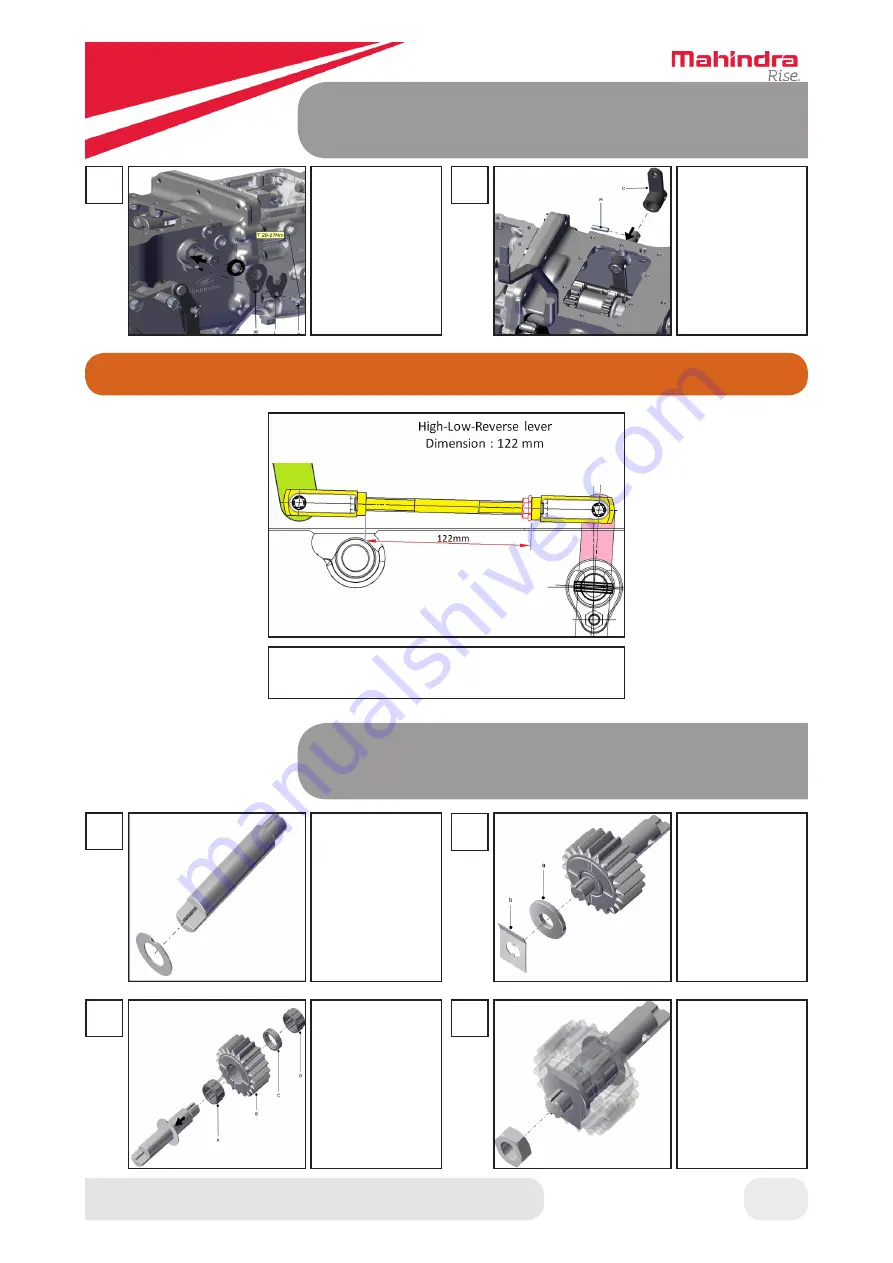
RANGE SHIFTER ASSEMBLY & MOUNTING
TRANSMISSION MAIN LINE ASSEMBLY
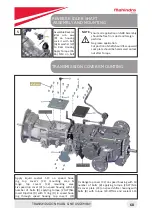
REVERSE IDLER SHAFT ASSEMBLY
AND MOUNTING
5
6
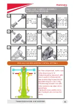
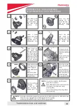
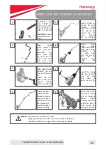
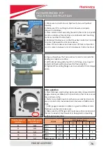
Press the oil seal
(O) on cross shaft.
Lock the cross
shaft with Wash
-
er
(W),
lock
plate (L) & bolt
(B) with Torque
( 2 0 - 2 7 ) N m
Lock Range cam
link outer (C) to
cross shaft us
-
ing Roll pin (R)
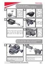
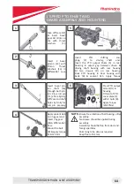
Insert the thrust
washer on re
-
verse idler shaft
NOTE-
Washer
notch to be oppo-
site to gear (B) as
shown in figure
Mount Gear (B)
on reverse idler
shaft with NRB
(A) spacer (C)
& NRB (D) in-
serted in gear.
3
1
2
Insert the spacer
(a) in the shaft and
above gearMount
the lock plate
(b) on the shaft
Fit the lock nut
and apply Torque
(41-46) Nm &
bend the lock
plate against
flat surface with
bending tool
4
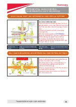
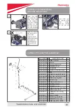
RANGE SHIFTER ASSEMBLY CRITICAL SETTINGS
Maintain Range Shifter lever length to 122 mm
⚠
67
Summary of Contents for Jivo 245 DI
Page 1: ...SERVICE MANUAL...
Page 4: ...GENERAL...
Page 6: ...PRODUCT SPECIFICATION GENERAL 6...
Page 8: ...MAINTENANCE...
Page 23: ...FRONT WIRING HARNESS LAYOUT MAINTENANCE 23...
Page 24: ...REAR WIRING HARNESS LAYOUT MAINTENANCE 24...
Page 25: ...4WD FRONT AXLE ASSEMBLY...
Page 26: ...BEARING OIL SEAL POSITION 4WD FRONT AXLE TORQUE VALUES 4WD FRONT AXLE ASSEMBLY 26...
Page 28: ...4WD FRONT AXLE OIL GREASE SPECIFICATIONS MAINTENANCE 28...
Page 42: ...TRANSMISSION...
Page 43: ...BEARING OIL SEAL POSITIONS TRANSMISSION TORQUE VALUES TRANSMISSION MAIN LINE ASSEMBLY 43...
Page 44: ...TRANSMISSION OIL AND GREASE SPECIFICATIONS TRANSMISSION MAIN LINE ASSEMBLY 44...
Page 69: ...ENGINE...
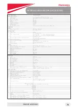
Page 70: ...DETAILED ENGINE SPECIFICATIONS ENGINE ASSEMBLY 70...

