30
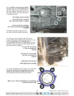
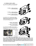
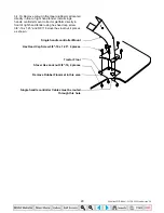
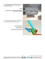
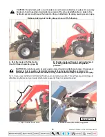
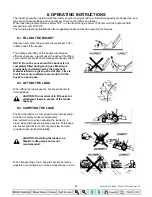
3.4.11. Route single handle controller cables through
platform hole then install spacer plate, single handle
controller with cables and cover plate using hex head
cap screw 5/16”-18 x 3.5”, flatwasher 5/16” and stover
hex locknut 5/16”-18 as shown. Install spacer in bottom
hole of single handle controller mount as shown.
Stover Hex Locknut 5/16”-18,
Flatwasher 5/16”, 3 places each
Cover Plate
Spacer
Single handle controller w/ Cables
Spacer Plate (Before tightening bolts position
Spacer Plate within ¼” of Fender then tighten all
bolts)
Hex Head Cap Screw 5/16”-18 x 3.5”, 3 places
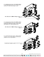
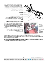
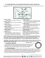
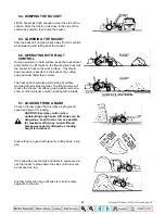
3.4.12. Make sure single handle controller is installed
with the single handle controller pivot point located to
the lower left corner of single handle controller housing.
This will ensure proper single handle controller
operation.
Front of Tractor
Single handle controller Pivot Point must be
located to the lower left of the Single handle
controller housing
Center of Tractor
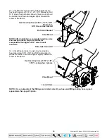
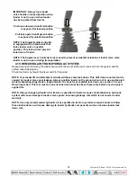
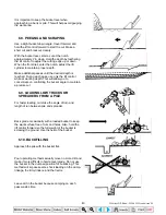
CRITICAL: Single handle controller rubber boot must be positioned and sealed correctly to prevent
moisture and contaminants from entering cables. Cable damage caused by moisture and/or contaminants
is not covered under loader warranty.
IMPORTANT: Always replace damaged rubber boot immediately. This will reduce the chance of cable and
controller damage caused by environmental contamination.
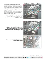
Bucket Circuit
Cable
connects to
this position
Lift Circuit
Cable
connects to
this position
35 Series 4WD, Model - 3535 & 4035 Loader June’08

