31
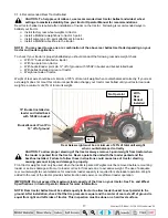
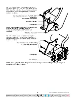
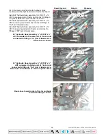
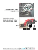
3.4.13. To allow handle to function correctly connect single handle controller to loader valve as described in next
step.
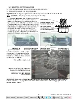
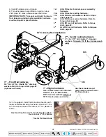
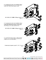
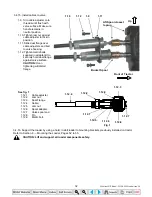
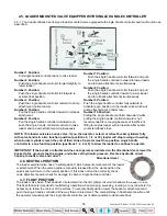
3.4.14. Install the following components to both
cables in order they are numbered.
1.1. Thread jam nut the entire length of
threads on cable so it rests on cable.
1.2. Slide dual flange on cable towards
nut.
1.3. Thread cable adjuster onto cable.
1.4. Thread nut onto end of cable to the
end of the threads.
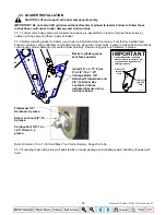
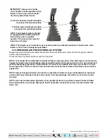
1.5.
CRITICAL:
Thread spool adapter onto
end of cable until the end of the cable
is flush with the inside of the spool
adapter.
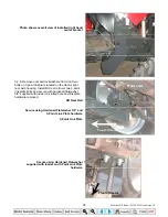
NOTE:
Move single handle
controller forward and rearward and
check to see which cable end moves.
Install this cable on top or lift spool of
valve. (Ref. page 32)
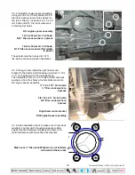
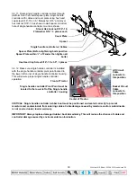
1.6. When installing cable to valve, install
pin through hole in spool adapter and
valve spool.
1.7. Lock (1.5) spool adapter in this
position using (1.4) nut. (Ref. page
32)
IMPORTANT: Make sure these
components are locked together
before completing cable
installation. Failure to follow these
instructions will allow cables to
come apart during operation.
1.8. Repeat procedure for additional cable.
1.1
1.2
1.3 1.4
1.5
1.6
35 Series 4WD, Model - 3535 & 4035 Loader June’08

