35
4.5. LOADER MOUNTED VALVE EQUIPPED WITH SINGLE HANDLE CONTROLLER
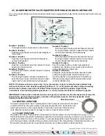
4.5.1. Your loader utilizes a series type loader mounted valve equipped with single handle controller and it will function as
described.
Number 1 Position:
Pull single handle controller back to raise loader.
Number 2 Position:
Push the single handle controller forward slightly to
lower loader.
Number 3 Position:
Push the single handle controller full forward to
activate float position.
Number 4 Position:
Push the single handle controller outward to dump
attachment (normal dump).
Number 5 Position:
Pull the single handle controller inward to roll back
attachment.
Number 6 Position:
Pull the single handle controller downward and
push the single handle controller outward to raise
loader and to dump attachment simultaneously.
Number 7 Position:
Push the single handle controller forward and push
the single handle controller outward to lower loader
and to dump attachment simultaneously.
Number 8 Position:
Push the single handle controller forward and pull
the single handle controller inward to lower loader
and to roll back attachment simultaneously.
Number 9 Position:
Push the single handle controller fully outward to
activate regen position on the loader valve which will
dump attachment at a faster rate.
Number 10 Position:
Pulling the single handle controller downward while
pulling the single handle controller inward is not
recommended for scooping because of insufficient
lifting force plus loader will not operate after bucket
contacts rollback stops.
NOTE: This loader valve is a series valve. If you, the operator, extend or retract bucket cylinders fully
with valve handle in a two function position (positions 6, 7, 8 or 10), loader will stop raising or lowering
when bucket cylinders reach the end of their stroke. Operator must then position single handle
controller to a one function position (positions 1, 2, 4 or 5) to allow the loader to continue to operate.
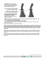
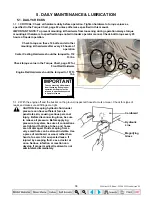
IMPORTANT: If the bucket or attachment does not operate as indicated on the directional decal, lower the
bucket to the ground, stop the engine, and relieve all hydraulic pressure. Recheck hydraulic circuit
hookup to loader valve and correct.
4.6. NEUTRAL POSITION
The loader external valve has a "neutral position" which prevents movement of the loader
or attachment. When the valve handle is manually released from the work position, the
valve spool will return to the neutral position. If this does not function correctly check
cable adjustment and/or check for damage to cable or single handle controller.
4.7. FLOAT POSITION
The loader valve has a "float position" incorporated into the lift cylinder circuit which allows the loader to float.
This float feature is important for satisfactory operation when scraping, sweeping, leveling, or any job where it is
necessary to follow the contour of the surface. To activate float position, lower the bucket or attachment and
push the single handle controller all the way forward into detent. The valve will stay in float detent position until
the operator manually pulls the single handle controller out of detent position to deactivate float.
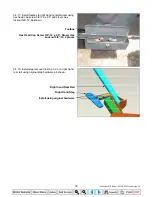
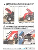
Directional decal
35 Series 4WD, Model - 3535 & 4035 Loader June’08

