67
15.1. SKID STEER BALE PROBE
IMPORTANT: This spear is a high strength alloy – drop forged steel and should not be welded or heat
treated.
IMPORTANT: Maximum load limit on super penetrator bale spear is 2,000 pounds. Do not handle round
bales that weigh over 1,200 pounds with this unit.
15.2. ASSEMBLY INSTRUCTIONS
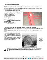
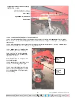
15.2.1. Install Bale Spears into tapered sleeves and
secure with nuts. Torque nuts as specified. Failure to
follow these instructions could cause damage to
spear and void your warranty.
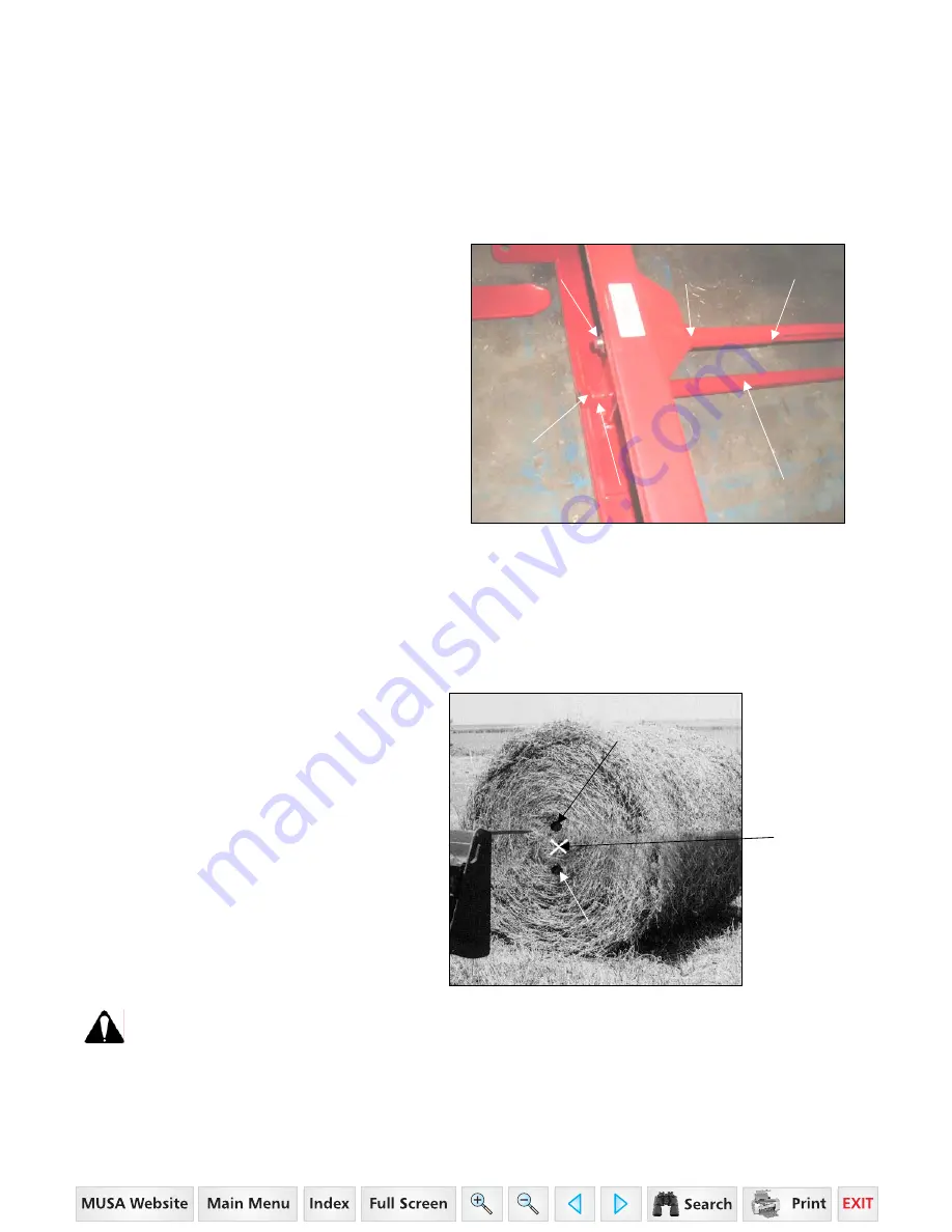
(1) Upper Spear (short spear)
(2) Tapered Sleeve
(3) Upper Spear Nut, 22mm.
Torque nut to 425 ft. lb.
(4) Lower Spear (long spear)
Flat surface of spear located upward.
(5) Tapered Sleeve.
(6) Lower Spear Nut, 28mm.
Torque nut to 515 ft. lb.
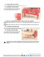
15.3. INSTALLATION INSTRUCTIONS TO SKID STEER TOOL CARRIER
IMPORTANT: Refer to Pages 61 to 63 for instructions concerning Installing Attachment to Skid Steer Tool
Carrier.
IMPORTANT: Refer to Page 64 for instructions concerning Removing Attachment from Skid Steer Tool
Carrier.
15.4. OPERATING INSTRUCTIONS
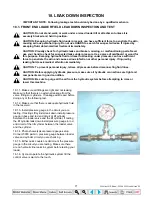
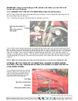
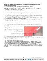
15.4.1. With bale spear level with ground, slowly
spear bale with top spear slightly above center of
the bale.
15.4.2. With both spears completely engaged into
bale, tilt bale spear slightly back from level and
transport the load in a low position.
Spear bale
slightly
above and
below
center of
bale.
CAUTION: Never park loader with Bale Spear or Pallet Fork attached to loader. Failure to follow
these instructions could cause instability of parked loader causing personal injury or property
damage.
Top spear location
Bottom spear location
2
1
3
6
5
4
35 Series 4WD, Model - 3535 & 4035 Loader June’08

