75
18.4.4. Place a load in the bucket and raise the boom slightly off the
ground. The load should be such that it induces a target reference
pressure between 1000 to 1500 psi in the cylinders refer to pressure
gauge previously installed.
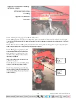
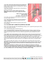
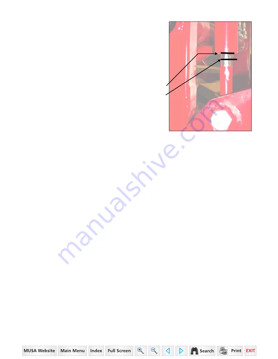
18.4.5. Place a mark using a permanent marker on the cylinder rod
at the end of the cylinder.
NOTE: Never mark the cylinder until the weight has been
applied to the loader and your pressure gauge reads 1000 to
1500 psi.
Measure from end of cylinder
after 10 minutes
Initial Mark on Tilt Cylinder Rod
18.4.6. After a 10 minute period of time measure the distance from
the end of cylinder to the mark.
18.4.7. If this distance has increased then some internal leakage is
present. If excessive leakage is found cylinder will need to be
replaced or repaired.
18.4.8. Lower the loader and bucket to the ground, and re-connect
the rod end hose.
18.5. TILT OR BUCKET CYLINDER VALVE SPOOL LEAKAGE
NOTE: Clean all parts thoroughly before disassembling any fittings. Cycle or operate the hydraulic system till the
control valve is warm to the touch.
18.5.1. Install a pressure gauge in the tilt circuit rod end
18.5.2. Cycle the tilt cylinders to full extend and then full retract a minimum of 5 times to expel any air in the
system. The cylinders should be cycled with the engine near maximum rpm. The bucket should not be loaded
during cycling. Use regen function of valve (if your loader is equipped with it) when expelling air from the tilt
circuit.
18.5.3. With the bucket lip approximately level and on the ground, place a load in the bucket and raise the boom
slightly off the ground. The load should be such that it induces a pressure of 1000 psi in the cylinder rod end.
Refer to pressure gauge previously installed. Place a mark using permanent marker on the cylinder rod at the end
of the cylinder after load has been applied. (Refer to previous page photo.) After a 10 minute period of time
measure the distance from the cylinder end to the mark to determine how much the cylinder has extended. Then
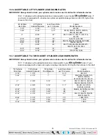
refer to Leak down Rate Chart in these instructions for the acceptable leak down rate for your specific cylinder
sizes.
18.5.4. If valve leak down rate is found to be more than allowable rate contact factory before returning valve.
IMPORTANT: These tests must be done very accurately to make sure the results are accurate. Any valve
that is returned and not found to exceed the manufacture's allowable leakage rate will not be covered
under warranty.
IMPORTANT: Contamination in hydraulic system will cause damage to the loader valve which will
increase valve spool leakage rates. If a returned valve is found to be damaged because of contamination
it will not be covered under warranty. Keep your hydraulic system maintained at all times and make sure
you clean all fittings and etc. when disconnecting or connecting hydraulic fittings.
35 Series 4WD, Model - 3535 & 4035 Loader June’08

