17
LOADER REMOVAL
STEP 4.
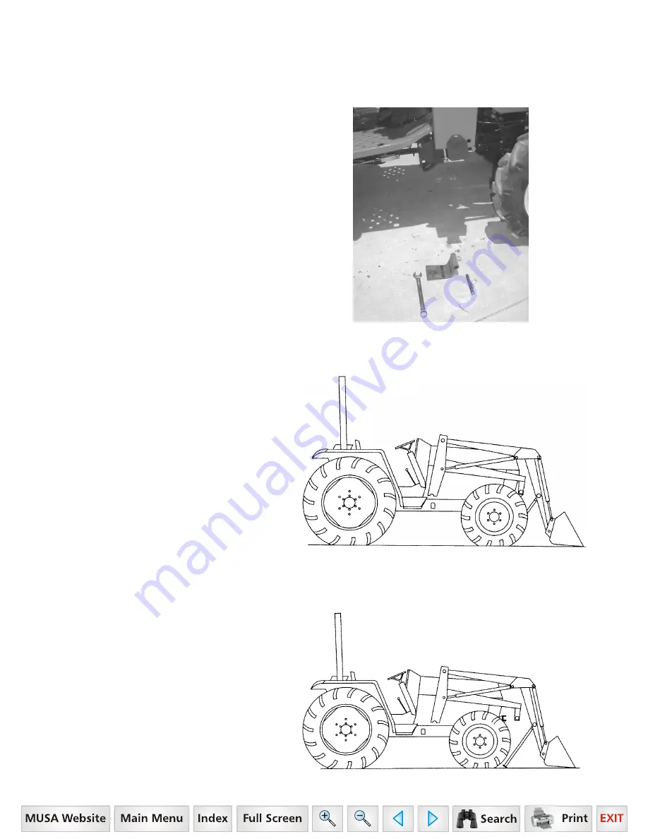
Remove hinge assembly
complete before parking loader off.
Remove hitch pin clip, clevis pin and hinge
assembly as shown. Reinstall washers and
nut to prevent loss. Replace hinge
assembly and hardware after loader has
been parked to prevent loss.
STEP 5.
Start the tractor and shift the
control valve (lift cylinder spool) into the
“float” position. Slowly retract the bucket
cylinders until the bottom of the bucket
rests firmly on the ground.
Note:
During this procedure the subframe
may raise off the Rear Mount. If necessary,
extend the lift cylinders as required to raise
the subframe clear of the rear mount.
Back the tractor up slowly until the
subframe front crosstube is just clear of the
Front Mount. Observe the four (4) hoses
(valve/tubelines) to ensure they are not
caught or stretched when backing away
from loader.
Shift the control valve (lift cylinder spool)
into the neutral position.
STEP 6.
Check to ensure the subframe will
clear the front tires. If additional clearance
is required, extend the lift cylinders.
Shut the tractor OFF then work valve
control lever to relieve hydraulic line
pressure and disconnect the four (4)
hydraulic hoses to ensure they will be clear
of the tractor.
Start the tractor and carefully back out of
the loader.
1
6
Series, Model - 2
816


