EN | 26 | ACX150/250 | Non-permanent junction
© MAHLE
10.5
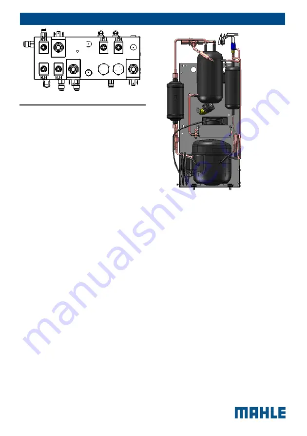
Suction unit chart
The suction unit is a group made up of
various pressurised equipments
interconnected through brazed piping,
which according to the PED directive fall
under article 3 paragraph 3.
A routine maintenance operation is the
replacement of the dryer filter, the
procedure of which is outlined in the user
manual.
Safety against the risk due to pressure of
the refrigerant fluid inside the suction unit
is ensured by a safety gauge installed
during manufacturing.
In case of replacement of the pressure
switch or the unit, use of new and original
spare parts not contaminated by other
substances is recommended as well as
requesting the declaration of conformity
proving the effective
test of the
components in the beginning.
The assistance centre is responsible for
workmanlike assembly and for checking
before new commissioning according to
the prescriptions provided for by the
regulations in force in the country of use;
in particular, the assistance centre will
have to guarantee that the assembly
ensures a perfect tightness and that the
safety components are installed
appropriately so as to ensure operation is
not jeopardized.
SUCTION UNIT Art. 3.3 (Dir. 97/23/EC)
11
Non-permanent
junction
Here below some instructions on the use
of Loctite® 577 on the thread of some
non-permanent junctions in the
pneumatic circuit of the ACX stations.
The product polymerizes when air is
absent and when in contact with
metal
;
its aim is preventing slackening caused
by impacts and vibrations. Yet, after
application and fixing onto the
junction/thread, you must tighten and
then wait several hours, in relation to the
type of coupling between metals, before
the product can get its maximum
performance in terms of hold/resistance.
For one’s own and other people’s safety,
the operator/user of the Loctite® 577
product must consider that it must be
employed in well-ventilated premises and
that protecting eyes and hands with
L T
V A I
R
HP SENSOR
LP SENSOR
TP SENSOR
CHECK VALVES
Summary of Contents for ACX150
Page 1: ...MAHLE ACX150 250 SERVICE MANUAL fflRHLE...
Page 3: ...EN 2 ACX150 250 Contents MAHLE 16 Diagnostic 30 16 1 Failure list 30...
Page 32: ...EN 31 ACX150 250 Diagnostic MAHLE ATTACHMENT 1 REFRIGERANT FLUID CIRCUIT ACX150 250...
Page 35: ...EN 34 ACX150 250 Diagnostic MAHLE Vacuum ACX150 250...
Page 36: ...EN 35 ACX150 250 Diagnostic MAHLE Oil injection ACX150 250...
Page 37: ...EN 36 ACX150 250 Diagnostic MAHLE Refrigerant recharge ACX150 250...
Page 83: ...DE 35 ACX150 250 Diagnose MAHLE ANHANG 1 REGELKREIS K LTEMITTEL ACX150 250...
Page 86: ...DE 38 ACX150 250 Diagnose MAHLE Vakuum ACX150 250...
Page 87: ...DE 39 ACX150 250 Diagnose MAHLE leinspritzung ACX150 250...
Page 88: ...DE 40 ACX150 250 Diagnose MAHLE Entladung K hlmittel ACX150 250...
Page 134: ...FR 34 ACX150 250 Diagnostic MAHLE ANNEXE 1 CIRCUIT DU LIQUIDE REFRIGERANT ACX150 250...
Page 137: ...FR 37 ACX150 250 Diagnostic MAHLE Vide ACX150 250...
Page 138: ...FR 38 ACX150 250 Diagnostic MAHLE Injection d huile ACX150 250...
Page 139: ...FR 39 ACX150 250 Diagnostic MAHLE R frig rant de recharge ACX150 250...
Page 150: ...FR 50 ACX150 250 Diagnostic MAHLE R FRIG RANT N EST PAS SUPPORT l analyseur...
Page 152: ...FR 52 ACX150 250 Diagnostic MAHLE...
Page 185: ...IT 33 ACX150 250 Diagnosi MAHLE ALLEGATO 1 CIRCUITO FLUIDO REFRIGERANTE ACX150 250...
Page 188: ...IT 36 ACX150 250 Diagnosi MAHLE Vuoto ACX150 250...
Page 189: ...IT 37 ACX150 250 Diagnosi MAHLE Iniezione olio ACX150 250...
Page 190: ...IT 38 ACX150 250 Diagnosi MAHLE Ricarica refrigerante ACX150 250...


